How to Use Lolin32 ESP32: Examples, Pinouts, and Specs
Introduction
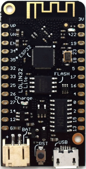
The Lolin32, manufactured by WeMos, is a compact development board based on the powerful ESP32 chip. It features integrated Wi-Fi and Bluetooth capabilities, making it an excellent choice for Internet of Things (IoT) projects and wireless communication applications. The board is designed to be user-friendly, with a small form factor and a USB interface for easy programming and power supply.
Explore Projects Built with Lolin32 ESP32

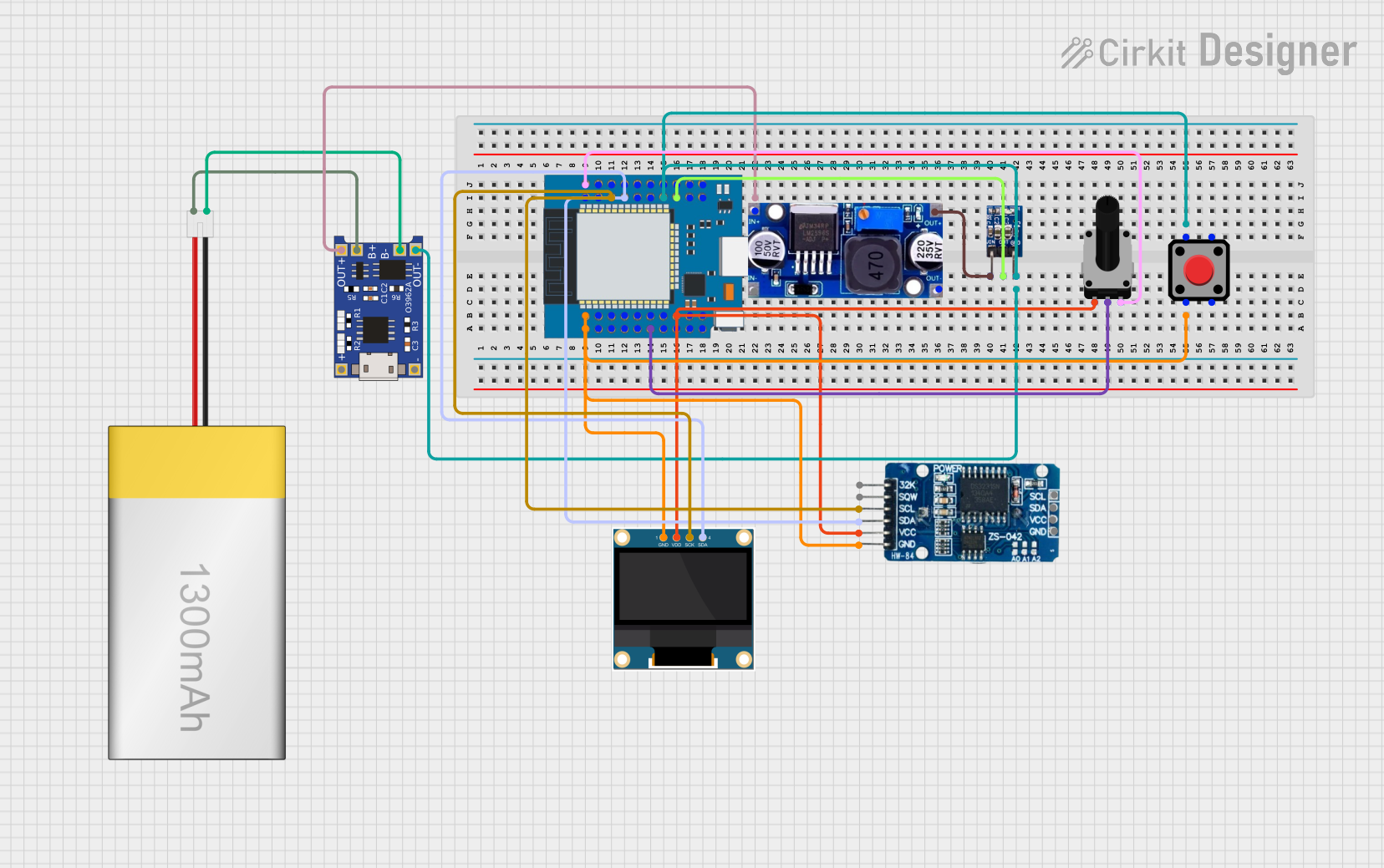
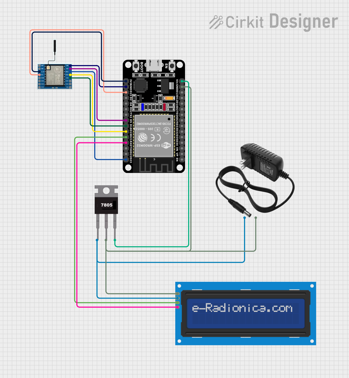
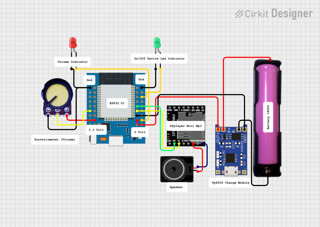
Explore Projects Built with Lolin32 ESP32
Common Applications and Use Cases
- IoT devices and smart home automation
- Wireless sensor networks
- Wearable technology
- Robotics and remote control systems
- Data logging and monitoring
- Prototyping and development of Wi-Fi/Bluetooth-enabled devices
Technical Specifications
The Lolin32 ESP32 board is built around the ESP32-WROOM-32 module, which combines a dual-core processor, wireless communication capabilities, and a variety of peripherals.
Key Technical Details
| Parameter | Specification |
|---|---|
| Microcontroller | ESP32 (Xtensa® dual-core 32-bit LX6) |
| Clock Speed | Up to 240 MHz |
| Flash Memory | 4 MB (onboard) |
| SRAM | 520 KB |
| Wi-Fi | 802.11 b/g/n |
| Bluetooth | v4.2 BR/EDR and BLE |
| Operating Voltage | 3.3V |
| Input Voltage (USB) | 5V |
| GPIO Pins | 32 |
| ADC Channels | 18 (12-bit resolution) |
| DAC Channels | 2 |
| Communication Interfaces | UART, SPI, I2C, I2S, CAN, PWM |
| Dimensions | 50 mm x 25.4 mm |
Pin Configuration and Descriptions
The Lolin32 board features a variety of pins for different functionalities. Below is the pinout description:
| Pin Name | Functionality | Notes |
|---|---|---|
| 3V3 | 3.3V Power Output | Provides 3.3V for external components |
| GND | Ground | Common ground for the circuit |
| EN | Enable | Active high, enables the chip |
| GPIO0 | General Purpose I/O, Boot Mode Select | Used for flashing firmware |
| GPIO2 | General Purpose I/O | Can be used as ADC or PWM |
| GPIO12 | General Purpose I/O | Can be used as ADC or PWM |
| GPIO13 | General Purpose I/O | Can be used as ADC or PWM |
| GPIO21 | SDA (I2C) | Default I2C data pin |
| GPIO22 | SCL (I2C) | Default I2C clock pin |
| TXD0 | UART0 Transmit | Serial communication TX |
| RXD0 | UART0 Receive | Serial communication RX |
For a complete pinout diagram, refer to the official WeMos documentation.
Usage Instructions
How to Use the Lolin32 in a Circuit
Powering the Board:
- Connect the Lolin32 to your computer or a USB power source using a micro-USB cable.
- Alternatively, you can power the board via the 3V3 pin with a regulated 3.3V supply.
Programming the Board:
- Install the Arduino IDE and add the ESP32 board support package.
- Select "Lolin32" as the board in the Arduino IDE.
- Connect the board to your computer and upload your code.
Connecting Peripherals:
- Use the GPIO pins to connect sensors, actuators, or other peripherals.
- Ensure that the voltage levels of connected devices are compatible with the 3.3V logic of the Lolin32.
Important Considerations and Best Practices
- Boot Mode: To flash firmware, hold down the "BOOT" button while pressing the "EN" button. Release the "EN" button first, then the "BOOT" button.
- Voltage Levels: Avoid applying voltages higher than 3.3V to the GPIO pins to prevent damage.
- Power Supply: If using an external power source, ensure it provides a stable 3.3V or 5V.
Example Code for Arduino UNO Integration
The following example demonstrates how to use the Lolin32 to read data from a DHT11 temperature and humidity sensor and send it to a serial monitor.
#include <DHT.h>

// Define the DHT sensor type and pin
#define DHTPIN 4      // GPIO4 is connected to the DHT11 data pin
#define DHTTYPE DHT11 // DHT11 sensor type

DHT dht(DHTPIN, DHTTYPE);

void setup() {
  Serial.begin(115200); // Initialize serial communication
  dht.begin();          // Initialize the DHT sensor
  Serial.println("DHT11 Sensor Test");
}

void loop() {
  delay(2000); // Wait 2 seconds between readings

  // Read temperature and humidity
  float humidity = dht.readHumidity();
  float temperature = dht.readTemperature();

  // Check if readings are valid
  if (isnan(humidity) || isnan(temperature)) {
    Serial.println("Failed to read from DHT sensor!");
    return;
  }

  // Print the results to the serial monitor
  Serial.print("Humidity: ");
  Serial.print(humidity);
  Serial.print("%  Temperature: ");
  Serial.print(temperature);
  Serial.println("°C");
}
Troubleshooting and FAQs
Common Issues and Solutions
The board is not detected by the computer:
- Ensure the USB cable is functional and supports data transfer.
- Install the correct USB-to-serial driver for the Lolin32.
Upload errors in the Arduino IDE:
- Check that the correct board and COM port are selected in the IDE.
- Hold the "BOOT" button while uploading the code to enter flash mode.
Wi-Fi connection issues:
- Verify the SSID and password in your code.
- Ensure the router is within range and supports 2.4 GHz Wi-Fi.
GPIO pin not working as expected:
- Confirm that the pin is not being used for another function (e.g., boot mode).
- Check for short circuits or incorrect wiring.
FAQs
Q: Can the Lolin32 be powered by a battery?
A: Yes, the Lolin32 has a JST connector for a LiPo battery. Ensure the battery voltage is within the supported range (3.7V nominal).
Q: How do I reset the board?
A: Press the "EN" button to reset the board.
Q: Can I use the Lolin32 with MicroPython?
A: Yes, the Lolin32 supports MicroPython. You can flash the MicroPython firmware to the board and use it for development.
Q: What is the maximum current output of the 3V3 pin?
A: The 3V3 pin can supply up to 500 mA, depending on the input power source.
This concludes the documentation for the Lolin32 ESP32 development board. For further details, refer to the official WeMos resources.