How to Use Load Sensor - 50kg: Examples, Pinouts, and Specs
Introduction
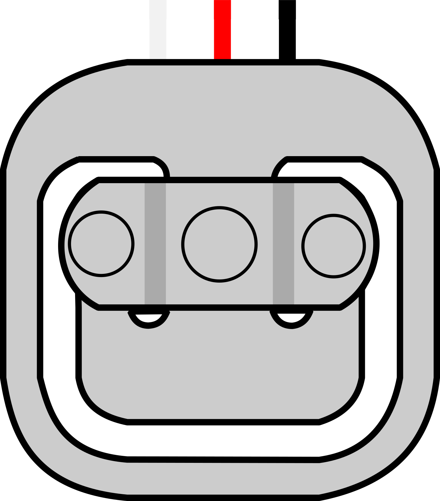
The Load Sensor - 50kg is an electronic device designed to measure weight or force up to 50 kilograms. It operates based on the principle of resistance change as the load is applied to the sensor. This sensor is commonly used in digital weighing scales, industrial systems for force measurement, and DIY projects that require weight sensing capabilities.
Explore Projects Built with Load Sensor - 50kg

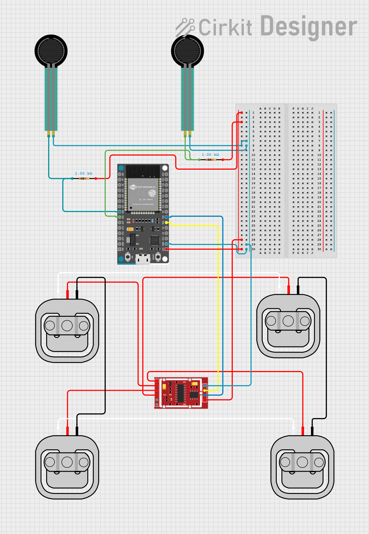
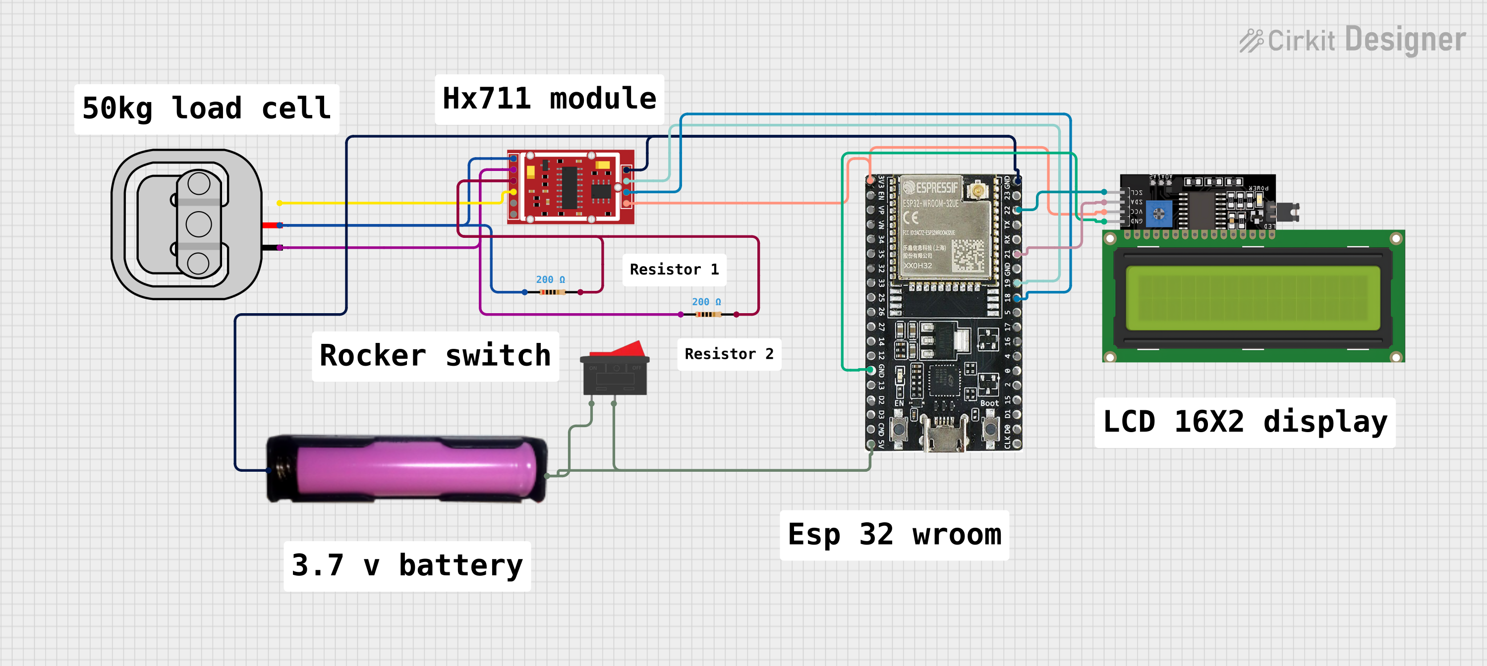

Explore Projects Built with Load Sensor - 50kg
Common Applications and Use Cases
- Digital weighing scales
- Industrial load measurements
- Force feedback for robotics
- Interactive installations that respond to weight changes
Technical Specifications
Key Technical Details
- Rated Load: 50kg
- Operating Voltage: Typically 5V to 10V
- Output Sensitivity: 1.0±0.1mV/V
- Non-linearity: ±0.05% F.S.
- Hysteresis: ±0.05% F.S.
- Repeatability: ±0.05% F.S.
- Creep (30 minutes): ±0.05% F.S.
- Temperature Effect on Output: ±0.002% F.S./°C
- Temperature Effect on Zero: ±0.002% F.S./°C
- Zero Balance: ±0.1 mV/V
- Input Resistance: 1000±10Ω
- Output Resistance: 1000±10Ω
- Insulation Resistance: ≥5000MΩ/50VDC
- Recommended Excitation Voltage: 5VDC to 10VDC
- Safe Overload: 120% F.S.
- Ultimate Overload: 150% F.S.
Pin Configuration and Descriptions
| Pin Number | Description | Notes |
|---|---|---|
| 1 | Excitation+ (E+) | Connect to positive voltage |
| 2 | Excitation- (E-) | Connect to ground |
| 3 | Signal+ (S+) | Output signal positive |
| 4 | Signal- (S-) | Output signal negative |
Usage Instructions
How to Use the Component in a Circuit
- Connect the E+ and E- pins to a stable power supply, typically 5V to 10V.
- Connect the S+ and S- pins to the input of a high-resolution analog-to-digital converter (ADC).
- Calibrate the sensor by applying known weights and recording the output voltage.
- Use the calibration data to convert the ADC readings into weight measurements.
Important Considerations and Best Practices
- Ensure that the sensor is mounted on a flat, stable surface to avoid measurement errors.
- Avoid exceeding the safe overload limit to prevent permanent damage to the sensor.
- Use a high-resolution ADC to capture the small voltage changes accurately.
- Implement temperature compensation in your design if the sensor will be used in varying temperature conditions.
Troubleshooting and FAQs
Common Issues Users Might Face
- Inaccurate Readings: This can be due to improper calibration, unstable power supply, or incorrect mounting of the sensor.
- No Output Signal: Check the connections to the power supply and ensure that the sensor is not damaged.
Solutions and Tips for Troubleshooting
- Calibration: Recalibrate the sensor periodically to maintain accuracy.
- Power Supply: Use a regulated power supply to ensure stable excitation voltage.
- Mounting: Verify that the sensor is mounted correctly and that the surface is not deforming under load.
FAQs
Q: Can I use multiple load sensors together for higher weight measurements?
- A: Yes, you can combine multiple sensors in a Wheatstone bridge configuration to measure higher weights.
Q: What should I do if the sensor's output drifts over time?
- A: Drift can be caused by temperature changes or sensor settling. Recalibrate the sensor and consider implementing temperature compensation.
Example Code for Arduino UNO
// Load Sensor - 50kg Example Code for Arduino UNO
#include <HX711.h>

// HX711 circuit wiring
const int LOADCELL_DOUT_PIN = 3;
const int LOADCELL_SCK_PIN = 2;

HX711 scale;

void setup() {
  Serial.begin(9600);
  scale.begin(LOADCELL_DOUT_PIN, LOADCELL_SCK_PIN);
}

void loop() {
  if (scale.is_ready()) {
    long reading = scale.read(); // Read data from the sensor
    Serial.print("Raw value: ");
    Serial.println(reading);
    // To convert the reading to kilograms, calibration is needed
  } else {
    Serial.println("Load sensor not ready");
  }
}
Note: The above code uses the HX711 library, which is a common ADC used with load cells. The scale.read() function returns the raw data which needs to be converted to weight using a calibration factor. This factor is determined by calibrating the sensor with known weights.
Remember to keep your code comments concise and within the 80 character line length limit.