
How to Use Relay: Examples, Pinouts, and Specs
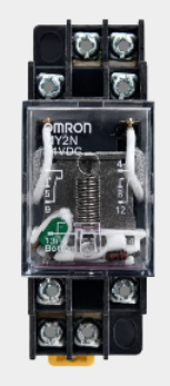
 Design with Relay in Cirkit Designer
Introduction
A relay is an electromechanical switch that uses an electromagnetic coil to open or close a circuit. It allows a low-power signal to control a higher power circuit, providing isolation and control in various applications. Relays are widely used in automation, home appliances, automotive systems, and industrial equipment to control high-current devices such as motors, lights, and heaters.
Explore Projects Built with Relay
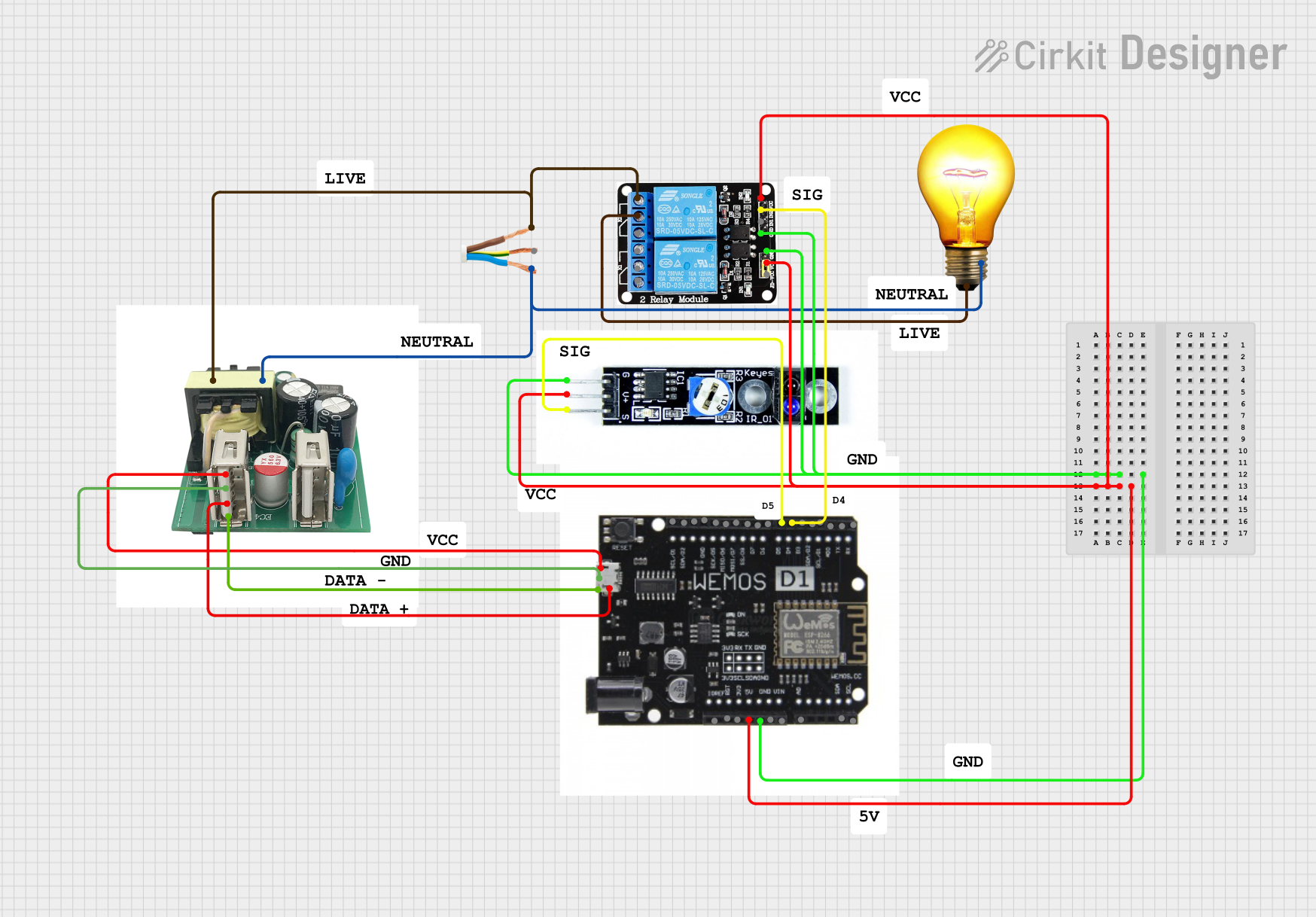 Open Project in Cirkit Designer
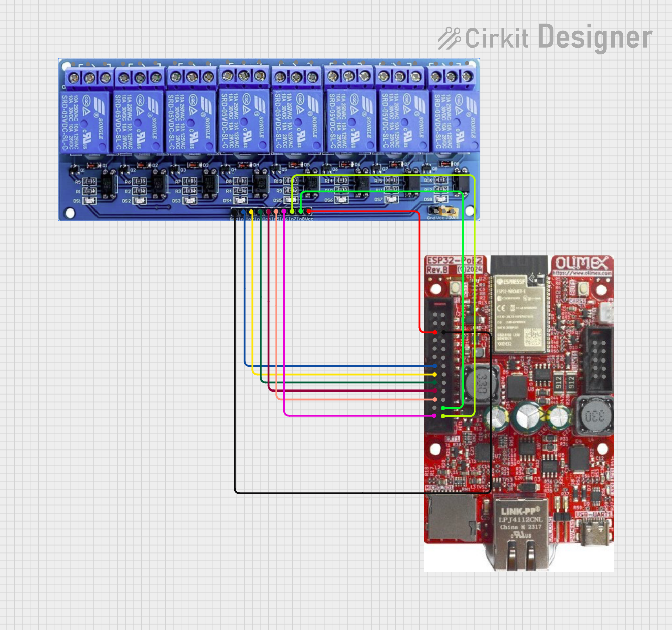 Open Project in Cirkit Designer
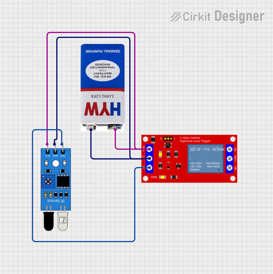 Open Project in Cirkit Designer
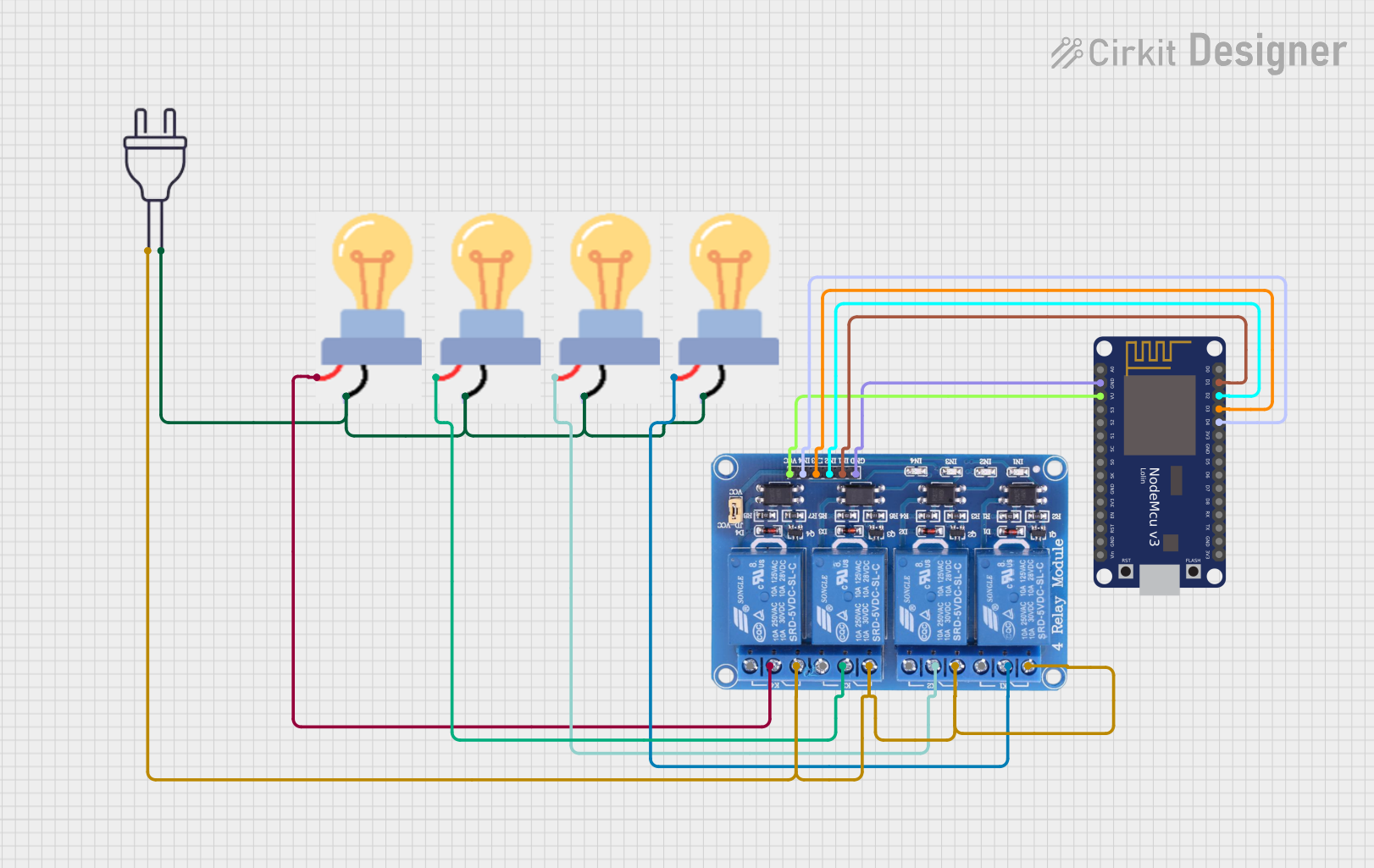 Open Project in Cirkit Designer
Explore Projects Built with Relay
Open Project in Cirkit DesignerOpen Project in Cirkit DesignerOpen Project in Cirkit DesignerOpen Project in Cirkit DesignerCommon Applications
- Home Automation: Controlling lights, fans, and other appliances.
- Automotive Systems: Switching headlights, horns, and other high-current loads.
- Industrial Equipment: Managing motors, pumps, and solenoids.
- Microcontroller Projects: Interfacing low-power microcontrollers with high-power devices.
Technical Specifications
Below are the general technical specifications for a standard 5V single-channel relay module:
Key Specifications
- Operating Voltage: 5V DC
- Trigger Voltage: 3.3V to 5V (logic level compatible)
- Maximum Switching Voltage: 250V AC / 30V DC
- Maximum Switching Current: 10A
- Coil Resistance: ~70Ω (varies by model)
- Isolation: Optocoupler isolation (on some modules)
- Relay Type: SPDT (Single Pole Double Throw)
Pin Configuration
The relay module typically has the following pins:
| Pin Name | Description |
|---|---|
| VCC | Power supply for the relay module (5V DC). |
| GND | Ground connection. |
| IN | Control signal input (logic HIGH activates the relay). |
| COM | Common terminal for the relay switch. |
| NO | Normally Open terminal (connected to COM when the relay is activated). |
| NC | Normally Closed terminal (connected to COM when the relay is not activated). |
Usage Instructions
How to Use a Relay in a Circuit
- Power the Relay Module: Connect the VCC pin to a 5V power source and the GND pin to ground.
- Control Signal: Connect the IN pin to a microcontroller's GPIO pin or another control signal source.
- Load Connection:
- Connect the device you want to control (e.g., a light bulb) to the NO terminal.
- Connect the power source for the load to the COM terminal.
- Trigger the Relay: Send a HIGH signal (3.3V or 5V) to the IN pin to activate the relay. This will close the circuit between COM and NO, powering the connected load.
Important Considerations
- Isolation: Use a relay module with optocoupler isolation for added safety when working with high voltages.
- Flyback Diode: If you're using a bare relay (not a module), add a flyback diode across the coil terminals to protect your circuit from voltage spikes.
- Current Ratings: Ensure the relay's current and voltage ratings match the requirements of your load.
- Power Supply: Use a stable 5V power supply to avoid relay malfunction.
Example: Controlling a Relay with Arduino UNO
Below is an example of how to control a relay module using an Arduino UNO:
// Define the pin connected to the relay module
const int relayPin = 7;

void setup() {
  pinMode(relayPin, OUTPUT); // Set the relay pin as an output
  digitalWrite(relayPin, LOW); // Ensure the relay is off initially
}

void loop() {
  digitalWrite(relayPin, HIGH); // Turn the relay on
  delay(1000); // Keep it on for 1 second
  digitalWrite(relayPin, LOW); // Turn the relay off
  delay(1000); // Keep it off for 1 second
}
Notes:
- Ensure the relay module is connected to the Arduino's 5V and GND pins.
- The relay will click when activated, indicating the switch is toggling.
Troubleshooting and FAQs
Common Issues
Relay Not Activating:
- Check if the VCC and GND connections are secure.
- Ensure the control signal voltage is within the relay's trigger range (3.3V to 5V).
- Verify the power supply provides sufficient current for the relay module.
Load Not Powering On:
- Confirm the load is properly connected to the NO and COM terminals.
- Check the load's power source and ensure it is functional.
- Verify the relay's current and voltage ratings match the load requirements.
Relay Stuck in One State:
- Inspect the relay for physical damage or wear.
- Ensure the control signal is toggling correctly.
FAQs
Q: Can I use a 3.3V microcontroller to control a 5V relay module?
A: Yes, most 5V relay modules can be triggered by a 3.3V control signal. However, check the module's datasheet to confirm compatibility.
Q: Is it safe to use a relay with high-voltage AC loads?
A: Yes, but ensure proper insulation and safety precautions. Use a relay with sufficient voltage and current ratings for the load.
Q: Why is my relay module making a buzzing sound?
A: This could be due to an unstable power supply or insufficient current. Ensure the power source is stable and meets the relay's requirements.
Q: Can I control multiple relays with one microcontroller?
A: Yes, as long as the microcontroller has enough GPIO pins and the relays' combined current draw does not exceed the microcontroller's power supply capacity.
By following this documentation, you can effectively use a relay in your projects while ensuring safety and reliability.