
How to Use DC power supply adapter: Examples, Pinouts, and Specs
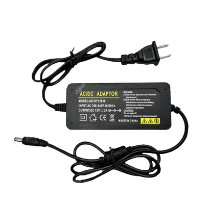
 Design with DC power supply adapter in Cirkit Designer
Introduction
A DC power supply adapter is a device that converts alternating current (AC) voltage from a wall outlet into a stable direct current (DC) voltage. It is widely used to power electronic devices such as microcontrollers, sensors, LED strips, and other low-voltage equipment. DC power supply adapters are available in various voltage and current ratings to suit different applications.
Explore Projects Built with DC power supply adapter
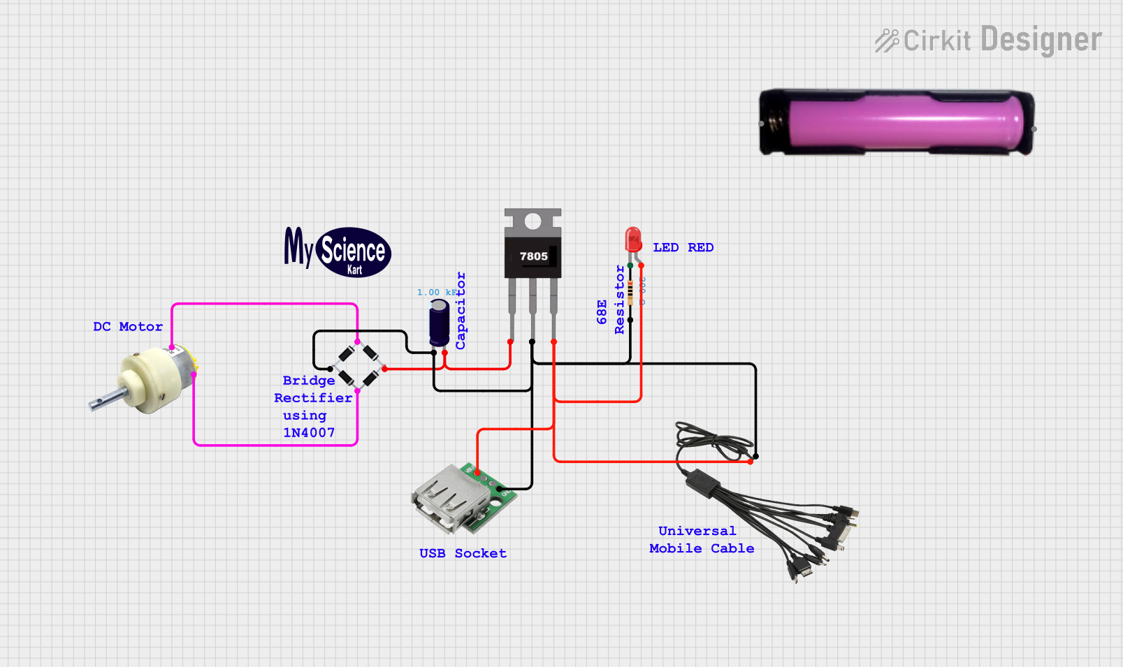 Open Project in Cirkit Designer
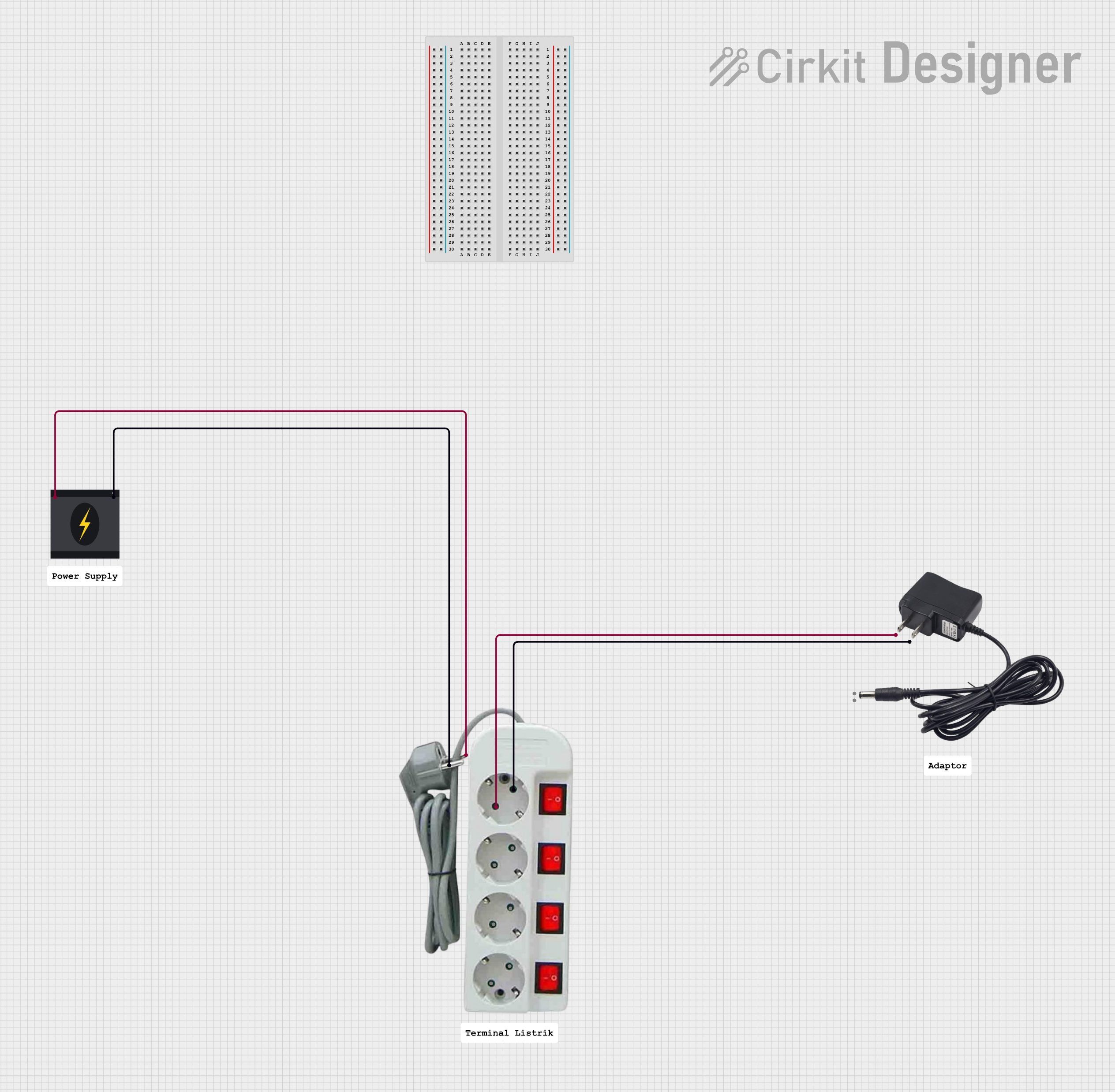 Open Project in Cirkit Designer
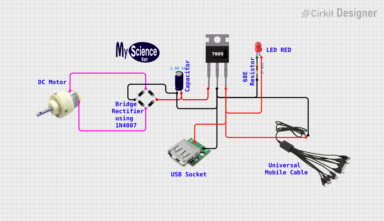 Open Project in Cirkit Designer
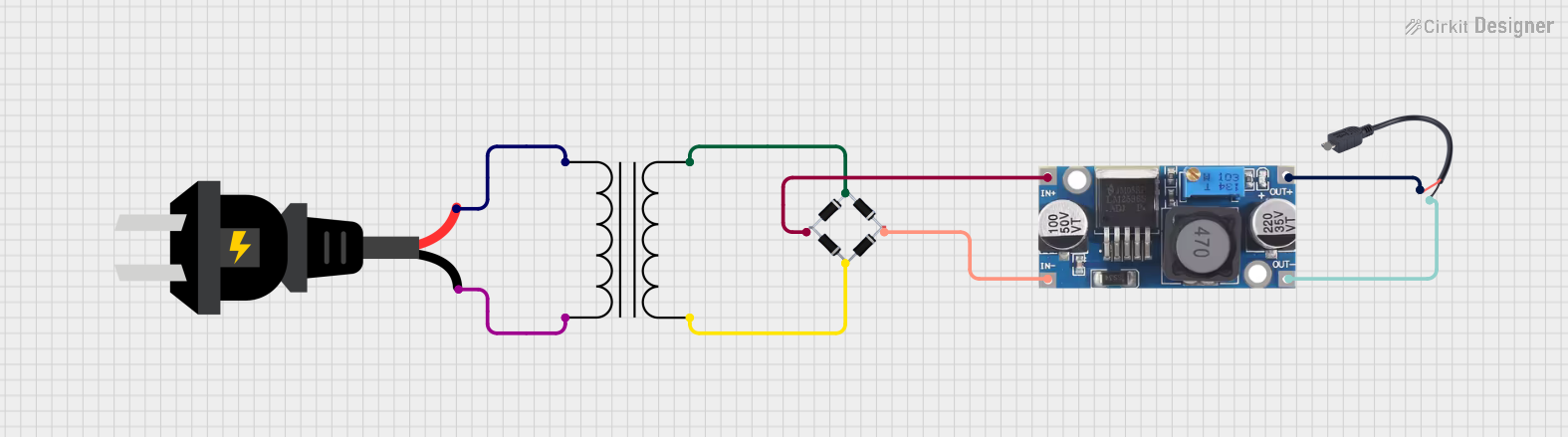 Open Project in Cirkit Designer
Explore Projects Built with DC power supply adapter
Open Project in Cirkit DesignerOpen Project in Cirkit DesignerOpen Project in Cirkit DesignerOpen Project in Cirkit DesignerCommon Applications and Use Cases
- Powering microcontroller boards (e.g., Arduino, Raspberry Pi)
- Supplying power to LED lighting systems
- Charging batteries for portable devices
- Operating small DC motors and actuators
- Providing power to audio equipment and other consumer electronics
Technical Specifications
Below are the general technical specifications for a typical DC power supply adapter. Note that specific models may vary in their ratings and features.
Key Technical Details
- Input Voltage: 100-240V AC, 50/60Hz
- Output Voltage: Common values include 5V, 9V, 12V, 24V DC
- Output Current: Typically ranges from 0.5A to 5A
- Power Rating: Varies based on voltage and current (e.g., 12W, 24W, 60W)
- Connector Type: Barrel jack (e.g., 5.5mm outer diameter, 2.1mm inner diameter)
- Polarity: Center-positive (most common) or center-negative
- Efficiency: 80% or higher (varies by model)
- Protection Features: Overvoltage, overcurrent, and short-circuit protection
Pin Configuration and Descriptions
The DC power supply adapter typically has a barrel jack connector with the following configuration:
| Pin/Section | Description |
|---|---|
| Outer Sleeve | Ground (GND) |
| Inner Pin | Positive DC voltage (V+) |
Note: Always verify the polarity of the adapter and the device it is powering to avoid damage.
Usage Instructions
How to Use the Component in a Circuit
- Select the Appropriate Adapter: Ensure the output voltage and current rating of the adapter match the requirements of your device.
- Verify Polarity: Check the polarity of the adapter and the device. Most adapters are center-positive, but always confirm before connecting.
- Connect to the Device: Plug the barrel jack into the power input port of your device.
- Power On: Plug the adapter into a wall outlet and switch it on (if applicable).
Important Considerations and Best Practices
- Voltage Matching: Using an adapter with a higher voltage than required can damage your device. Always match the voltage rating.
- Current Rating: The adapter's current rating should meet or exceed the device's current requirement. An adapter with insufficient current capacity may overheat or fail.
- Polarity Check: Incorrect polarity can permanently damage your device. Double-check the polarity markings on both the adapter and the device.
- Avoid Overloading: Do not connect devices that exceed the adapter's power rating.
- Ventilation: Ensure the adapter has adequate ventilation to prevent overheating during prolonged use.
Example: Using a DC Power Supply Adapter with an Arduino UNO
To power an Arduino UNO using a 12V DC adapter:
- Verify that the adapter provides 12V DC with a center-positive polarity.
- Plug the barrel jack into the Arduino's power input port.
- Connect the adapter to a wall outlet.
- The Arduino will automatically regulate the 12V input to its required operating voltage.
Here is an example Arduino sketch to test the setup:
// Simple LED blink program for Arduino UNO
// Ensure the Arduino is powered by a 12V DC adapter

const int ledPin = 13; // Built-in LED pin on Arduino UNO

void setup() {
  pinMode(ledPin, OUTPUT); // Set the LED pin as an output
}

void loop() {
  digitalWrite(ledPin, HIGH); // Turn the LED on
  delay(1000);               // Wait for 1 second
  digitalWrite(ledPin, LOW);  // Turn the LED off
  delay(1000);               // Wait for 1 second
}
Troubleshooting and FAQs
Common Issues Users Might Face
Device Not Powering On
- Cause: Incorrect voltage or polarity.
- Solution: Verify the adapter's voltage and polarity match the device's requirements.
Adapter Overheating
- Cause: Overloading the adapter by connecting a device that draws more current than the adapter's rating.
- Solution: Use an adapter with a higher current rating.
Intermittent Power
- Cause: Loose connection or damaged cable.
- Solution: Check the barrel jack connection and inspect the cable for damage.
Device Malfunctioning
- Cause: Noise or instability in the adapter's output voltage.
- Solution: Use a higher-quality adapter with better voltage regulation.
Solutions and Tips for Troubleshooting
- Test with a Multimeter: Measure the adapter's output voltage to ensure it matches the specified rating.
- Inspect the Connector: Ensure the barrel jack fits snugly into the device's power port.
- Check for Damage: Look for frayed wires, cracks, or other signs of wear on the adapter.
- Use a Compatible Adapter: If the original adapter is unavailable, choose a replacement with identical voltage, current, and polarity specifications.
By following these guidelines, you can safely and effectively use a DC power supply adapter in your electronic projects.