Cirkit Designer Logo
Cirkit Designer
Your all-in-one circuit design IDE
Home / 
Component Documentation

How to Use SPW2430: Examples, Pinouts, and Specs

Image of SPW2430
Cirkit Designer LogoDesign with SPW2430 in Cirkit Designer

Introduction

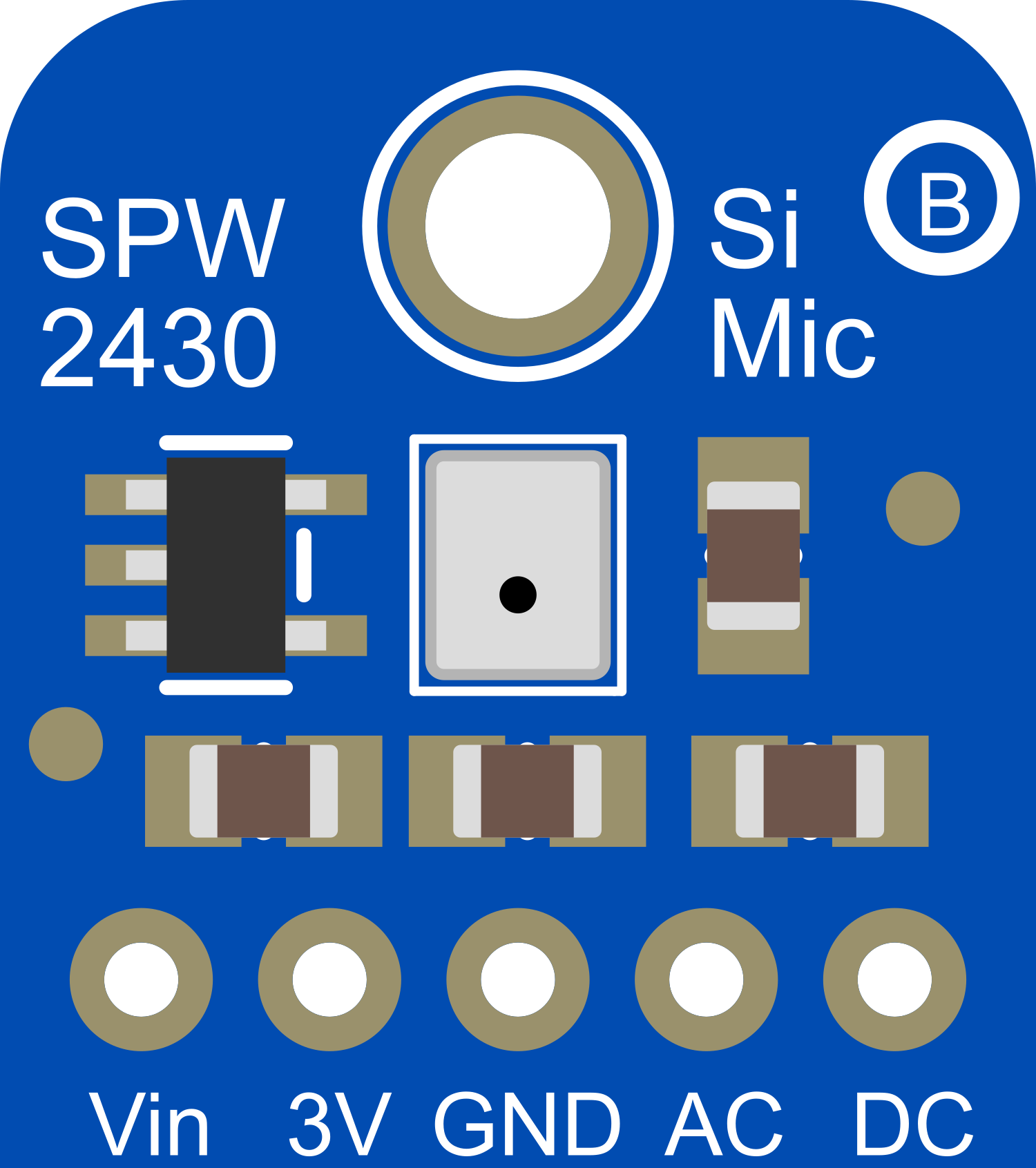
The SPW2430 is a compact, high-performance analog MEMS microphone sensor that is well-suited for a variety of applications requiring sound detection. Its small form factor and high sensitivity make it ideal for voice recognition, audio recording, and noise detection tasks. The SPW2430 is commonly used in mobile devices, smart home applications, and other electronics where audio input is necessary.

Explore Projects Built with SPW2430

Use Cirkit Designer to design, explore, and prototype these projects online. Some projects support real-time simulation. Click "Open Project" to start designing instantly!
ESP32C3 and SIM800L Powered Smart Energy Monitor with OLED Display and Wi-Fi Connectivity
Image of master: A project utilizing SPW2430 in a practical application
This circuit is a power monitoring system that uses an ESP32C3 microcontroller to collect power usage data from slave devices via WiFi and SMS. The collected data is displayed on a 0.96" OLED screen, and the system is powered by an AC-DC converter module. Additionally, the circuit includes a SIM800L GSM module for SMS communication and LEDs for status indication.
Cirkit Designer LogoOpen Project in Cirkit Designer
ESP32-S3 Based Vibration Detection System with TFT Display and Power Backup
Image of IOT Thesis: A project utilizing SPW2430 in a practical application
This circuit features an ESP32-S3 microcontroller connected to various peripherals including an ADXL355 accelerometer, an SW-420 vibration sensor, a buzzer module, and an ILI9341 TFT display. The ESP32-S3 manages sensor inputs and provides output to the display and buzzer. Power management is handled by a 12V to 5V step-down converter, and a UPS ensures uninterrupted power supply, with a rocker switch to control the power flow.
Cirkit Designer LogoOpen Project in Cirkit Designer
Satellite Compass and Network-Integrated GPS Data Processing System
Image of GPS 시스템 측정 구성도_241016: A project utilizing SPW2430 in a practical application
This circuit comprises a satellite compass, a mini PC, two GPS antennas, power supplies, a network switch, media converters, and an atomic rubidium clock. The satellite compass is powered by a triple output DC power supply and interfaces with an RS232 splitter for 1PPS signals. The mini PCs are connected to the USRP B200 devices via USB for data and power, and to media converters via Ethernet, which in turn connect to a network switch using fiber optic links. The antennas are connected to the USRP B200s through RF directional couplers, and the atomic clock provides a 1PPS input to the RS232 splitter.
Cirkit Designer LogoOpen Project in Cirkit Designer
Battery-Powered UPS with Step-Down Buck Converter and BMS
Image of Mini ups: A project utilizing SPW2430 in a practical application
This circuit is a power management system that steps down a 240V AC input to a lower DC voltage using a buck converter, which then powers a 40W UPS. The UPS is controlled by a rocker switch and is backed up by a battery management system (BMS) connected to three 3.7V batteries in series, ensuring continuous power supply.
Cirkit Designer LogoOpen Project in Cirkit Designer

Explore Projects Built with SPW2430

Use Cirkit Designer to design, explore, and prototype these projects online. Some projects support real-time simulation. Click "Open Project" to start designing instantly!
Image of master: A project utilizing SPW2430 in a practical application
ESP32C3 and SIM800L Powered Smart Energy Monitor with OLED Display and Wi-Fi Connectivity
This circuit is a power monitoring system that uses an ESP32C3 microcontroller to collect power usage data from slave devices via WiFi and SMS. The collected data is displayed on a 0.96" OLED screen, and the system is powered by an AC-DC converter module. Additionally, the circuit includes a SIM800L GSM module for SMS communication and LEDs for status indication.
Cirkit Designer LogoOpen Project in Cirkit Designer
Image of IOT Thesis: A project utilizing SPW2430 in a practical application
ESP32-S3 Based Vibration Detection System with TFT Display and Power Backup
This circuit features an ESP32-S3 microcontroller connected to various peripherals including an ADXL355 accelerometer, an SW-420 vibration sensor, a buzzer module, and an ILI9341 TFT display. The ESP32-S3 manages sensor inputs and provides output to the display and buzzer. Power management is handled by a 12V to 5V step-down converter, and a UPS ensures uninterrupted power supply, with a rocker switch to control the power flow.
Cirkit Designer LogoOpen Project in Cirkit Designer
Image of GPS 시스템 측정 구성도_241016: A project utilizing SPW2430 in a practical application
Satellite Compass and Network-Integrated GPS Data Processing System
This circuit comprises a satellite compass, a mini PC, two GPS antennas, power supplies, a network switch, media converters, and an atomic rubidium clock. The satellite compass is powered by a triple output DC power supply and interfaces with an RS232 splitter for 1PPS signals. The mini PCs are connected to the USRP B200 devices via USB for data and power, and to media converters via Ethernet, which in turn connect to a network switch using fiber optic links. The antennas are connected to the USRP B200s through RF directional couplers, and the atomic clock provides a 1PPS input to the RS232 splitter.
Cirkit Designer LogoOpen Project in Cirkit Designer
Image of Mini ups: A project utilizing SPW2430 in a practical application
Battery-Powered UPS with Step-Down Buck Converter and BMS
This circuit is a power management system that steps down a 240V AC input to a lower DC voltage using a buck converter, which then powers a 40W UPS. The UPS is controlled by a rocker switch and is backed up by a battery management system (BMS) connected to three 3.7V batteries in series, ensuring continuous power supply.
Cirkit Designer LogoOpen Project in Cirkit Designer

Technical Specifications

Key Technical Details

  • Supply Voltage (Vdd): 1.5V to 3.6V
  • Current Consumption: 250 µA (typical)
  • Sensitivity: -42 dBV/Pa (typical)
  • Signal to Noise Ratio (SNR): 65 dB A-weighted (typical)
  • Frequency Response: 100 Hz to 10 kHz
  • Output Impedance: 200 Ohms (typical)
  • Operating Temperature Range: -40°C to +85°C

Pin Configuration and Descriptions

Pin Number Name Description
1 Vdd Power supply voltage (1.5V to 3.6V)
2 GND Ground connection
3 OUT Analog output signal

Usage Instructions

Integration into a Circuit

To use the SPW2430 in a circuit:

  1. Connect the Vdd pin to a power supply within the specified voltage range.
  2. Connect the GND pin to the ground of the circuit.
  3. The OUT pin provides the analog output signal, which can be connected to an analog-to-digital converter (ADC) or an amplifier for further processing.

Important Considerations and Best Practices

  • Ensure that the power supply voltage does not exceed the maximum rating to prevent damage to the sensor.
  • Place the microphone sensor away from sources of mechanical vibration and airflow to avoid interference.
  • Use proper decoupling capacitors close to the Vdd pin to minimize power supply noise.
  • For optimal performance, the sensor should be mounted in an acoustically appropriate location and orientation.

Example Code for Arduino UNO

// SPW2430 Microphone Sensor Example for Arduino UNO

const int micPin = A0; // Analog pin connected to microphone OUT
int micValue = 0;      // Variable to store the mic input

void setup() {
  Serial.begin(9600); // Start serial communication at 9600 baud
}

void loop() {
  micValue = analogRead(micPin); // Read the input from the microphone
  Serial.println(micValue);      // Print the value to the serial monitor
  delay(10);                     // Short delay for stability
}

Troubleshooting and FAQs

Common Issues

  • Low Signal Output: Ensure that the sensor is receiving the correct voltage and check for any loose connections.
  • High Noise Levels: Verify that the sensor is placed away from noise sources and that proper decoupling techniques are used.
  • Inconsistent Readings: Check for any interference from nearby electronic devices and ensure that the sensor is not subjected to mechanical vibrations.

Solutions and Tips

  • Use a pre-amplifier to boost the microphone signal before feeding it to an ADC.
  • Implement a low-pass filter to reduce high-frequency noise and improve signal quality.
  • If using long cables, shield the microphone lines to reduce electromagnetic interference.

FAQs

Q: Can the SPW2430 be used with a 5V power supply? A: No, the maximum supply voltage for the SPW2430 is 3.6V. Using a 5V power supply may damage the sensor.

Q: How can I improve the sensitivity of the microphone? A: Sensitivity can be improved by using an external amplifier and carefully positioning the microphone for optimal sound capture.

Q: Is the SPW2430 capable of detecting the direction of sound? A: The SPW2430 is an omnidirectional microphone sensor and does not inherently detect the direction of sound. Multiple sensors can be used in an array to achieve directional sensing.

Remember to always refer to the manufacturer's datasheet for the most accurate and detailed information about the SPW2430 microphone sensor.