Cirkit Designer Logo
Cirkit Designer
Your all-in-one circuit design IDE
Home / 
Component Documentation

How to Use SparkFun AST-CAN485 IO Shield 24V: Examples, Pinouts, and Specs

Image of SparkFun AST-CAN485 IO Shield 24V
Cirkit Designer LogoDesign with SparkFun AST-CAN485 IO Shield 24V in Cirkit Designer

Introduction

The SparkFun AST-CAN485 IO Shield is an electronic component designed to facilitate communication between a microcontroller, such as an Arduino, and devices using the CAN (Controller Area Network) protocol. This shield operates at 24V, making it suitable for industrial applications where higher voltage levels are common. It is an ideal choice for automotive systems, home automation, and other projects requiring robust communication between various electronic devices.

Explore Projects Built with SparkFun AST-CAN485 IO Shield 24V

Use Cirkit Designer to design, explore, and prototype these projects online. Some projects support real-time simulation. Click "Open Project" to start designing instantly!
ESP32-Based Motion Tracking System with ICM20948 Sensor
Image of ICM20948: A project utilizing SparkFun AST-CAN485 IO Shield 24V in a practical application
This circuit features a SparkFun ESP32 Thing Plus microcontroller interfaced with an Adafruit ICM20948 9-axis motion sensor via an Adafruit TXB0104 4-channel bi-directional level shifter. The ESP32 reads data from the ICM20948 sensor, calculates orientation angles such as pitch, roll, yaw, and azimuth, and outputs these values to the serial monitor. The level shifter ensures compatibility between the 3.3V logic levels of the ESP32 and the 1.8V logic levels required by the ICM20948.
Cirkit Designer LogoOpen Project in Cirkit Designer
Arduino UNO R4 WiFi Controlled Dissolved Ozone Monitoring System with RS485 and LCD Display
Image of ProCon: A project utilizing SparkFun AST-CAN485 IO Shield 24V in a practical application
This circuit features an Arduino UNO R4 WiFi microcontroller connected to an RS485 module for serial communication with a dissolved ozone sensor, whose readings are displayed on a 2.4" LCD. A joystick provides user input, and a power supply module converts 220V AC to 24V DC for the sensor. The Arduino's embedded code orchestrates the sensor data acquisition, display updates, and user interaction.
Cirkit Designer LogoOpen Project in Cirkit Designer
Arduino Nano and SX1278 LoRa Communication Module
Image of Jurutera Muda (Receiver): A project utilizing SparkFun AST-CAN485 IO Shield 24V in a practical application
This circuit integrates an Arduino Nano with an SX1278 LoRa transceiver module via an I/O Expansion Shield for SPI communication. It is designed for long-range wireless data transmission, with the Arduino Nano serving as the central processing unit to control the LoRa module. The provided code is a placeholder, suggesting that the user-specific application logic is yet to be developed.
Cirkit Designer LogoOpen Project in Cirkit Designer
ESP32-Based Wi-Fi Controlled 24V Input/Output Interface Module
Image of ESP32 4 på rad: A project utilizing SparkFun AST-CAN485 IO Shield 24V in a practical application
This circuit uses an ESP32 microcontroller to interface with a 3.3V PNP to 24V NPN photoelectric isolation module, which in turn connects to a 40-pin connector for general-purpose input and output. The 24V power supply provides the necessary voltage for the isolation module and the 40-pin connector, enabling the ESP32 to control and monitor high-voltage signals safely.
Cirkit Designer LogoOpen Project in Cirkit Designer

Explore Projects Built with SparkFun AST-CAN485 IO Shield 24V

Use Cirkit Designer to design, explore, and prototype these projects online. Some projects support real-time simulation. Click "Open Project" to start designing instantly!
Image of ICM20948: A project utilizing SparkFun AST-CAN485 IO Shield 24V in a practical application
ESP32-Based Motion Tracking System with ICM20948 Sensor
This circuit features a SparkFun ESP32 Thing Plus microcontroller interfaced with an Adafruit ICM20948 9-axis motion sensor via an Adafruit TXB0104 4-channel bi-directional level shifter. The ESP32 reads data from the ICM20948 sensor, calculates orientation angles such as pitch, roll, yaw, and azimuth, and outputs these values to the serial monitor. The level shifter ensures compatibility between the 3.3V logic levels of the ESP32 and the 1.8V logic levels required by the ICM20948.
Cirkit Designer LogoOpen Project in Cirkit Designer
Image of ProCon: A project utilizing SparkFun AST-CAN485 IO Shield 24V in a practical application
Arduino UNO R4 WiFi Controlled Dissolved Ozone Monitoring System with RS485 and LCD Display
This circuit features an Arduino UNO R4 WiFi microcontroller connected to an RS485 module for serial communication with a dissolved ozone sensor, whose readings are displayed on a 2.4" LCD. A joystick provides user input, and a power supply module converts 220V AC to 24V DC for the sensor. The Arduino's embedded code orchestrates the sensor data acquisition, display updates, and user interaction.
Cirkit Designer LogoOpen Project in Cirkit Designer
Image of Jurutera Muda (Receiver): A project utilizing SparkFun AST-CAN485 IO Shield 24V in a practical application
Arduino Nano and SX1278 LoRa Communication Module
This circuit integrates an Arduino Nano with an SX1278 LoRa transceiver module via an I/O Expansion Shield for SPI communication. It is designed for long-range wireless data transmission, with the Arduino Nano serving as the central processing unit to control the LoRa module. The provided code is a placeholder, suggesting that the user-specific application logic is yet to be developed.
Cirkit Designer LogoOpen Project in Cirkit Designer
Image of ESP32 4 på rad: A project utilizing SparkFun AST-CAN485 IO Shield 24V in a practical application
ESP32-Based Wi-Fi Controlled 24V Input/Output Interface Module
This circuit uses an ESP32 microcontroller to interface with a 3.3V PNP to 24V NPN photoelectric isolation module, which in turn connects to a 40-pin connector for general-purpose input and output. The 24V power supply provides the necessary voltage for the isolation module and the 40-pin connector, enabling the ESP32 to control and monitor high-voltage signals safely.
Cirkit Designer LogoOpen Project in Cirkit Designer

Common Applications and Use Cases

  • Automotive electronics (e.g., connecting sensors and actuators)
  • Industrial control systems
  • Home automation networks
  • Robotics communication interfaces
  • Data logging and telemetry systems

Technical Specifications

Key Technical Details

  • Operating Voltage: 24V
  • Communication Protocol: CAN (Controller Area Network)
  • Compatible with Arduino and other microcontrollers
  • Extended temperature range for industrial environments

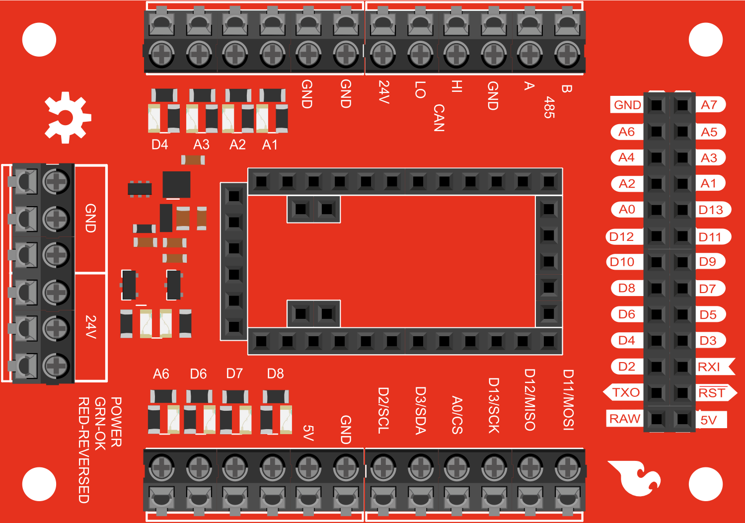
Pin Configuration and Descriptions

Pin Number Description Notes
1 CAN_H CAN High
2 CAN_L CAN Low
3 GND Ground
4 V+ (24V) Supply Voltage
5 NC Not Connected
6 NC Not Connected
7 Digital IO Configurable digital input/output
8 Analog Input Analog sensor input

Usage Instructions

How to Use the Component in a Circuit

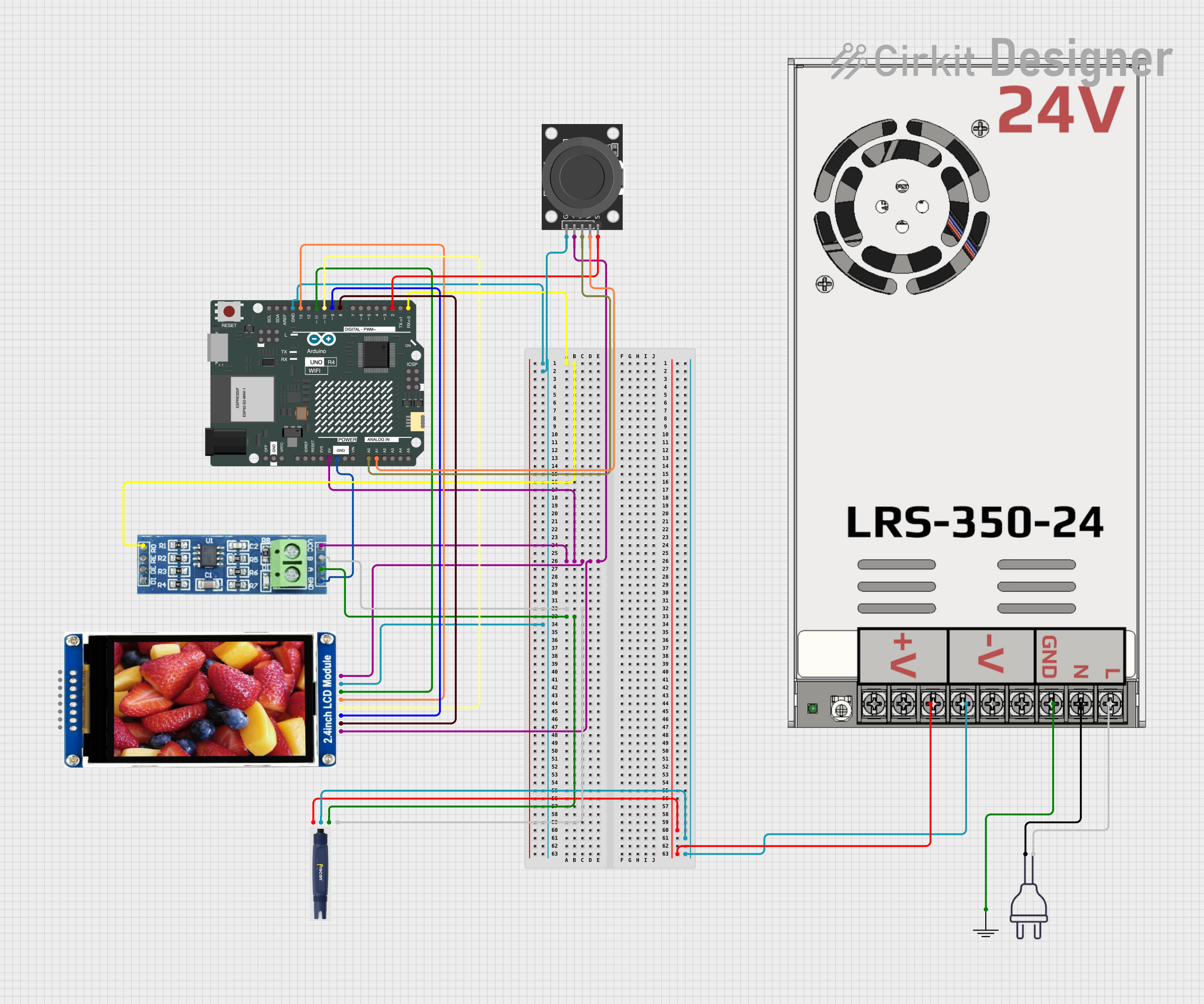
  1. Power Supply: Ensure that the shield is powered with a stable 24V supply.
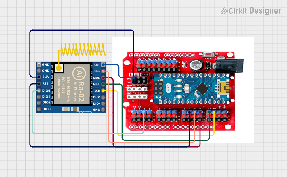
  2. Connection to Microcontroller: Attach the shield to your Arduino or compatible microcontroller.
  3. CAN Bus Connection: Connect the CAN_H and CAN_L pins to your CAN network.
  4. Digital/Analog IO: Utilize the digital and analog pins for additional sensors or actuators as needed.

Important Considerations and Best Practices

  • Always verify the power supply voltage and polarity before connecting the shield.
  • Use twisted-pair cables for CAN_H and CAN_L connections to reduce noise.
  • Ensure proper termination of the CAN network with a 120-ohm resistor.
  • Avoid long wire runs and follow proper grounding practices to minimize interference.

Troubleshooting and FAQs

Common Issues Users Might Face

  • Communication Errors: Check the wiring and termination resistors on the CAN bus.
  • No Power to the Shield: Verify the power supply and connections to the V+ and GND pins.
  • Inconsistent Readings from IO Pins: Ensure that there is no electrical noise affecting the signals and that the pins are configured correctly in the software.

Solutions and Tips for Troubleshooting

  • Double-check all connections for solid contact and correct orientation.
  • Use an oscilloscope to monitor the CAN signals for proper levels and integrity.
  • Implement software error handling to detect and recover from communication faults.

FAQs

Q: Can I use this shield with a 5V Arduino? A: Yes, the shield is compatible with 5V Arduinos, but the CAN network operates at 24V.

Q: How do I program the Arduino to communicate over CAN? A: You will need to use a CAN library for Arduino, such as the MCP_CAN library, to handle the CAN communication.

Q: What is the maximum length for the CAN bus wiring? A: The maximum length depends on the baud rate; for lower baud rates, longer lengths are possible. Typically, up to 40 meters at 1 Mbps is acceptable.

Example Arduino Code

#include <mcp_can.h>
#include <SPI.h>

// Initialize CAN controller at CS pin 10
MCP_CAN CAN0(10);

void setup() {
  Serial.begin(115200);
  
  // Initialize CAN controller at 500 kbps
  if (CAN0.begin(MCP_ANY, CAN_500KBPS, MCP_8MHZ) == CAN_OK) {
    Serial.println("CAN controller initialized");
  } else {
    Serial.println("CAN controller initialization failed");
  }
  
  // Set normal operation mode
  CAN0.setMode(MCP_NORMAL);
}

void loop() {
  // Check for incoming messages
  if (CAN0.checkReceive() == CAN_MSGAVAIL) {
    unsigned char len = 0;
    unsigned char buf[8];
    
    // Read data: len = data length, buf = data byte(s)
    CAN0.readMsgBuf(&len, buf);
    
    // Print received message
    for (int i = 0; i < len; i++) {
      Serial.print(buf[i], HEX);
      Serial.print(" ");
    }
    Serial.println();
  }
}

Note: This example assumes the use of the MCP_CAN library for handling CAN communication. Ensure that the library is installed in your Arduino IDE before compiling and uploading the code to your microcontroller.