How to Use Microwave Radar Doppler Motion Sensor Module: Examples, Pinouts, and Specs
Introduction
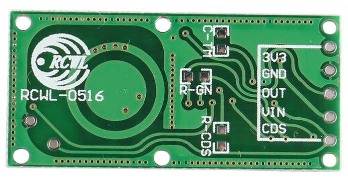
The Microwave Radar Doppler Motion Sensor Module is a highly sensitive motion detection device that operates using microwave radar technology. It detects motion by measuring the Doppler effect of reflected microwave signals, making it capable of sensing movement through non-metallic objects such as walls, glass, and plastic. Unlike traditional PIR (Passive Infrared) sensors, this module is not affected by ambient temperature changes, making it ideal for a wide range of applications.
Explore Projects Built with Microwave Radar Doppler Motion Sensor Module
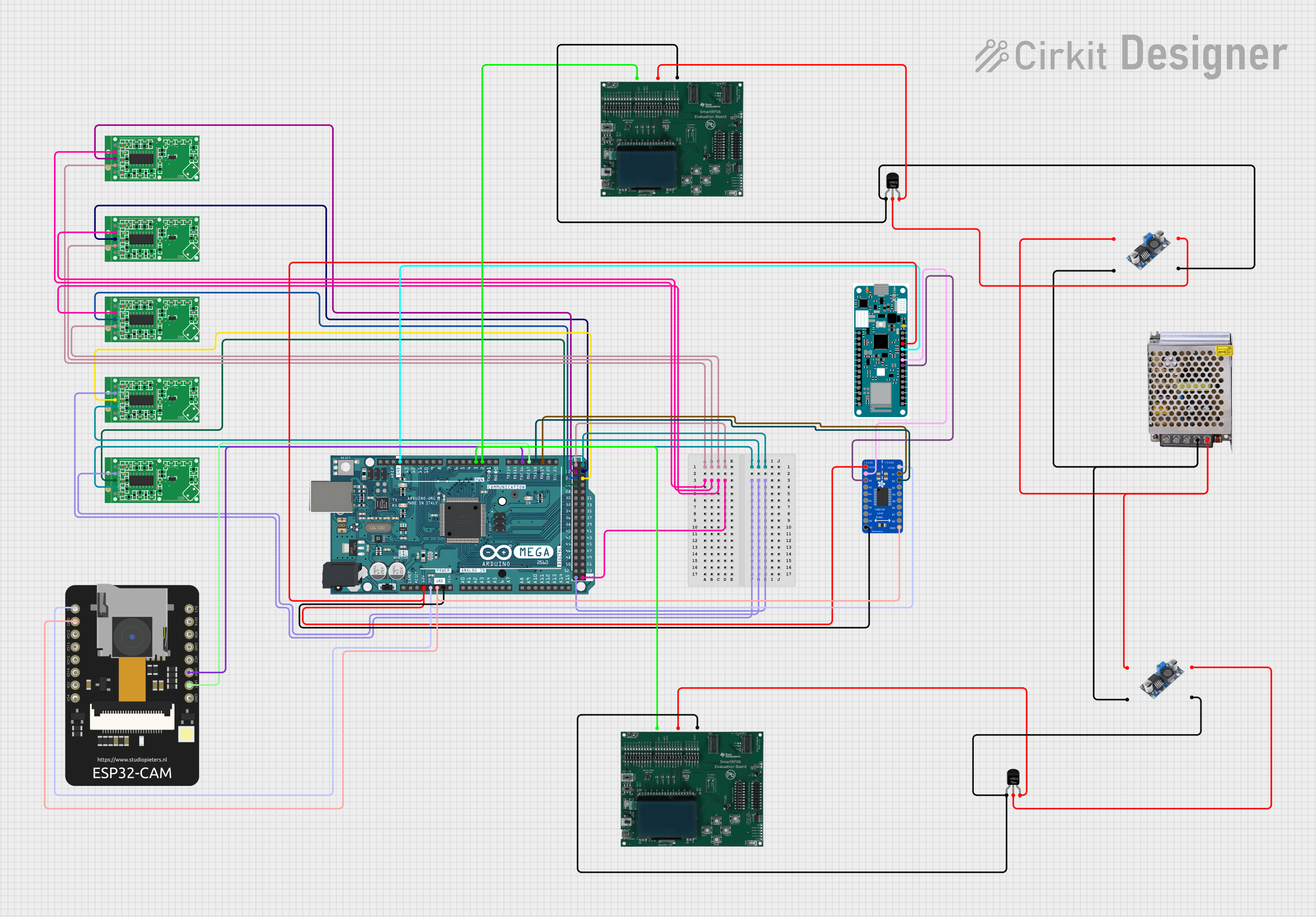

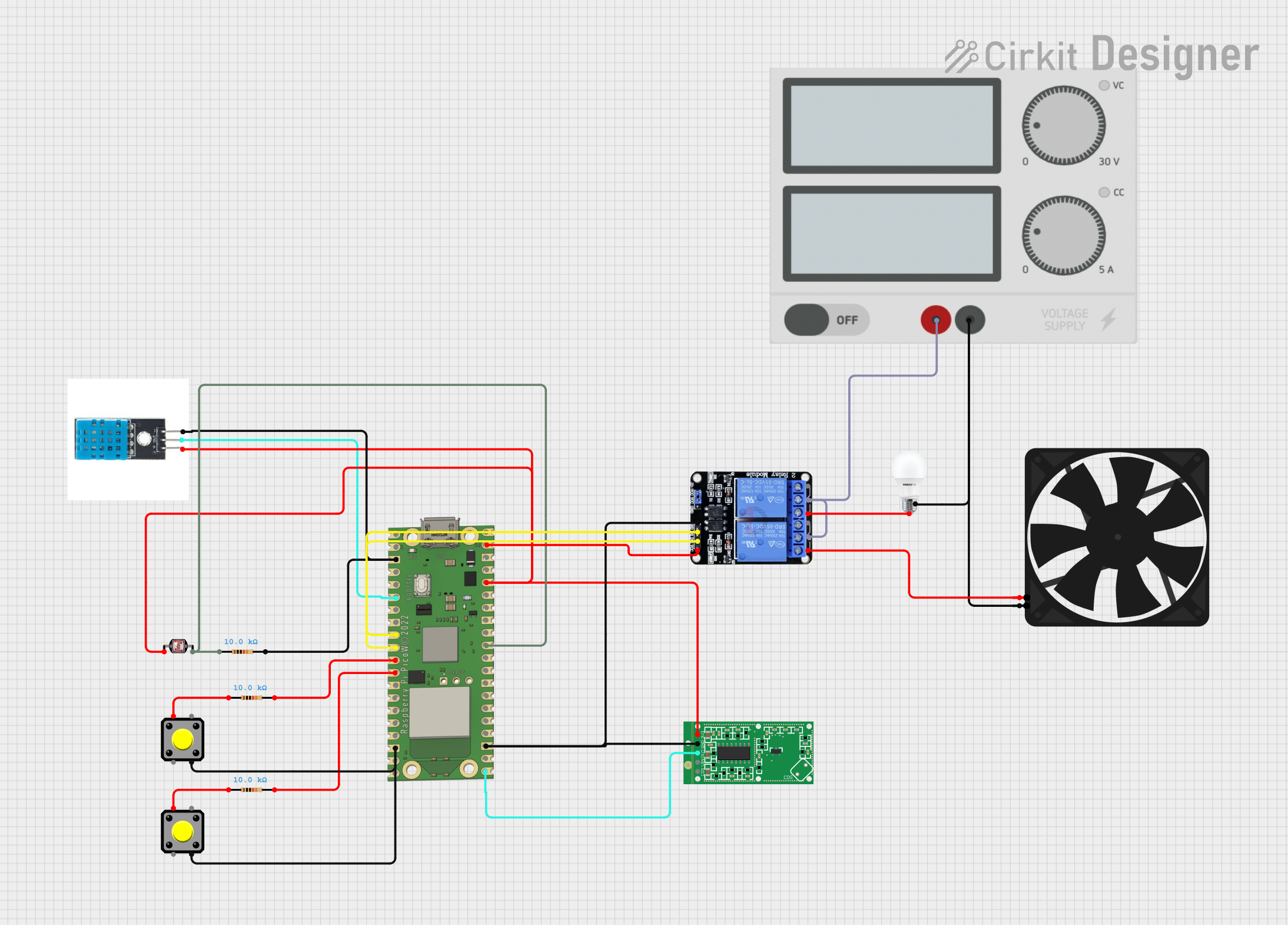
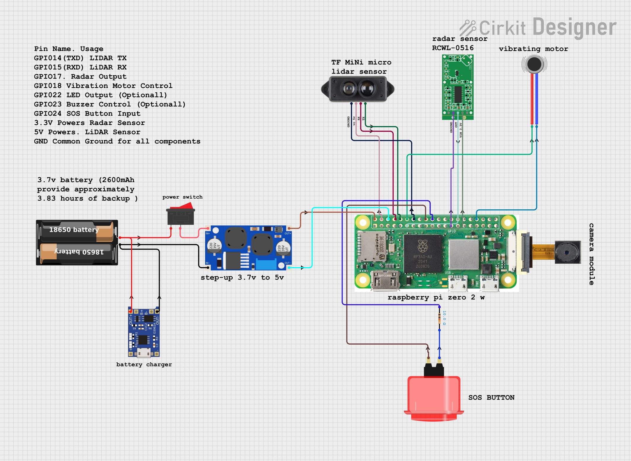
Explore Projects Built with Microwave Radar Doppler Motion Sensor Module
Common Applications and Use Cases
- Security systems for motion detection
- Automatic lighting systems
- Industrial automation and robotics
- Smart home devices
- Occupancy detection in offices and public spaces
Technical Specifications
The following table outlines the key technical details of the Microwave Radar Doppler Motion Sensor Module:
| Parameter | Value |
|---|---|
| Operating Voltage | 4.0V to 28.0V DC |
| Operating Current | ≤ 3mA |
| Detection Range | 5 to 15 meters (adjustable) |
| Operating Frequency | 10.525 GHz |
| Output Voltage (High) | 3.3V |
| Output Voltage (Low) | 0V |
| Output Signal Type | Digital (High/Low) |
| Detection Angle | 360° (omnidirectional) |
| Operating Temperature | -20°C to +80°C |
| Dimensions | ~35mm x 17mm x 8mm |
Pin Configuration and Descriptions
The module typically has three or four pins, depending on the specific model. Below is the pin configuration:
| Pin | Name | Description |
|---|---|---|
| 1 | VCC | Power supply input (4.0V to 28.0V DC). |
| 2 | GND | Ground connection. |
| 3 | OUT | Digital output pin. Outputs HIGH (3.3V) when motion is detected, LOW (0V) otherwise. |
| 4* | EN (optional) | Enable pin for controlling the module (not present on all models). |
*Note: The EN pin is optional and may not be available on all versions of the module.
Usage Instructions
How to Use the Component in a Circuit
- Power the Module: Connect the
VCCpin to a DC power source (4.0V to 28.0V) and theGNDpin to ground. - Connect the Output: Connect the
OUTpin to a microcontroller input pin or directly to a load (e.g., an LED or relay) for motion detection. - Adjust Sensitivity and Range: Some modules include potentiometers or jumpers to adjust the detection range and sensitivity. Refer to the specific module's datasheet for details.
- Test the Module: Once connected, the module will output a HIGH signal (3.3V) when motion is detected and LOW (0V) when no motion is present.
Important Considerations and Best Practices
- Avoid Metal Obstructions: The module's microwave signals can penetrate non-metallic materials but are blocked by metal. Ensure there are no metallic objects in the detection path.
- Placement: Install the module in a location where it has a clear line of sight to the area being monitored. Avoid placing it near sources of interference, such as Wi-Fi routers or other RF devices.
- Power Supply: Use a stable DC power source to avoid erratic behavior.
- Delay Time: Some modules have a built-in delay time after motion is detected. This delay is typically fixed but may be adjustable on certain models.
Example: Connecting to an Arduino UNO
Below is an example of how to connect the Microwave Radar Doppler Motion Sensor Module to an Arduino UNO and use it to control an LED:
Circuit Diagram
- Connect the
VCCpin of the module to the Arduino's5Vpin. - Connect the
GNDpin of the module to the Arduino'sGNDpin. - Connect the
OUTpin of the module to Arduino digital pin2. - Connect an LED to Arduino digital pin
13(with a 220-ohm resistor in series).
Arduino Code
// Define the pin connections
const int motionPin = 2;  // Pin connected to the module's OUT pin
const int ledPin = 13;    // Pin connected to the LED

void setup() {
  pinMode(motionPin, INPUT);  // Set motionPin as input
  pinMode(ledPin, OUTPUT);    // Set ledPin as output
  Serial.begin(9600);         // Initialize serial communication
}

void loop() {
  int motionDetected = digitalRead(motionPin);  // Read the motion sensor output

  if (motionDetected == HIGH) {  // If motion is detected
    digitalWrite(ledPin, HIGH); // Turn on the LED
    Serial.println("Motion detected!"); // Print message to serial monitor
  } else {
    digitalWrite(ledPin, LOW);  // Turn off the LED
    Serial.println("No motion."); // Print message to serial monitor
  }

  delay(100);  // Small delay to stabilize readings
}
Troubleshooting and FAQs
Common Issues and Solutions
No Motion Detected:
- Ensure the module is powered correctly (check
VCCandGNDconnections). - Verify that the detection range and sensitivity are properly adjusted.
- Check for obstructions in the detection path.
- Ensure the module is powered correctly (check
False Triggers:
- Avoid placing the module near sources of RF interference (e.g., Wi-Fi routers).
- Ensure the module is not exposed to strong vibrations or rapid temperature changes.
Output Signal Not Changing:
- Confirm that the
OUTpin is connected to the correct input pin on the microcontroller. - Check the power supply voltage to ensure it is within the specified range.
- Confirm that the
FAQs
Q: Can the module detect motion through walls?
A: Yes, the module can detect motion through non-metallic walls, glass, and plastic. However, the detection range may be reduced depending on the material's thickness and density.
Q: How does this module compare to PIR sensors?
A: Unlike PIR sensors, which rely on detecting infrared radiation, this module uses microwave radar technology. It is less affected by ambient temperature changes and can detect motion through certain materials.
Q: Can I use this module outdoors?
A: The module can operate in a wide temperature range (-20°C to +80°C), but it should be protected from direct exposure to rain or moisture to ensure reliable operation.
Q: Is the detection range adjustable?
A: Yes, many modules include a potentiometer or jumper to adjust the detection range. Refer to your specific module's datasheet for details.