Cirkit Designer Logo
Cirkit Designer
Your all-in-one circuit design IDE
Home / 
Component Documentation

How to Use mpi3508: Examples, Pinouts, and Specs

Image of mpi3508
Cirkit Designer LogoDesign with mpi3508 in Cirkit Designer

Introduction

The MPI3508 is a high-performance, low-power microcontroller designed for embedded applications. It features multiple I/O ports, analog-to-digital conversion (ADC) capabilities, and support for various communication protocols, making it a versatile choice for a wide range of projects. Its compact design and energy efficiency make it ideal for applications such as IoT devices, robotics, industrial automation, and consumer electronics.

Explore Projects Built with mpi3508

Use Cirkit Designer to design, explore, and prototype these projects online. Some projects support real-time simulation. Click "Open Project" to start designing instantly!
Arduino Mega 2560 Based Security System with Fingerprint Authentication and SMS Alerts
Image of Door security system: A project utilizing mpi3508 in a practical application
This circuit features an Arduino Mega 2560 microcontroller interfaced with a SIM800L GSM module, two fingerprint scanners, an I2C LCD display, an IR sensor, and a piezo buzzer. Power management is handled by a PowerBoost 1000 Basic Pad USB, a TP4056 charging module, and a Li-ion 18650 battery, with an option to use a Mini AC-DC 110V-230V to 5V 700mA module for direct power supply. The primary functionality appears to be a security system with GSM communication capabilities, biometric access control, and visual/audible feedback.
Cirkit Designer LogoOpen Project in Cirkit Designer
Battery-Powered Raspberry Pi Pico GPS Tracker with Sensor Integration
Image of Copy of CanSet v1: A project utilizing mpi3508 in a practical application
This circuit is a data acquisition and communication system powered by a LiPoly battery and managed by a Raspberry Pi Pico. It includes sensors (BMP280, MPU9250) for environmental data, a GPS module for location tracking, an SD card for data storage, and a WLR089-CanSAT for wireless communication. The TP4056 module handles battery charging, and a toggle switch controls power distribution.
Cirkit Designer LogoOpen Project in Cirkit Designer
ESP32-Powered Obstacle Avoidance Robot with IR and Ultrasonic Sensors
Image of projcememek: A project utilizing mpi3508 in a practical application
This circuit features a 18650 Li-Ion battery connected to a TP4056 charging module, which in turn is connected to an MT3608 boost converter to step up the voltage. The output of the MT3608 powers an ESP32 microcontroller, a TCRT 5000 IR sensor, an HC-SR04 ultrasonic sensor, and an MG996R servo motor. The ESP32 is configured to control the servo motor via GPIO 27 and to receive input signals from the IR sensor and ultrasonic sensor through GPIO 14 and GPIO 13, respectively.
Cirkit Designer LogoOpen Project in Cirkit Designer
Automated Peristaltic Pump Control System with Arduino and ESP32
Image of Long-Term Bench: A project utilizing mpi3508 in a practical application
This circuit appears to be a control system for peristaltic pumps and a motor driver, with power regulation and communication capabilities. It includes a main power supply stepping down from 48V to various lower voltages for different components, two tb6600 micro stepping motor drivers controlling peristaltic pumps, and an ESP32-based custom PCB for managing signals and communication. The system also integrates an Arduino Mega for additional control and interfacing with a Sensirion flow meter, RS232 to TTL converters for serial communication, and an ultrasonic sensor for distance measurement.
Cirkit Designer LogoOpen Project in Cirkit Designer

Explore Projects Built with mpi3508

Use Cirkit Designer to design, explore, and prototype these projects online. Some projects support real-time simulation. Click "Open Project" to start designing instantly!
Image of Door security system: A project utilizing mpi3508 in a practical application
Arduino Mega 2560 Based Security System with Fingerprint Authentication and SMS Alerts
This circuit features an Arduino Mega 2560 microcontroller interfaced with a SIM800L GSM module, two fingerprint scanners, an I2C LCD display, an IR sensor, and a piezo buzzer. Power management is handled by a PowerBoost 1000 Basic Pad USB, a TP4056 charging module, and a Li-ion 18650 battery, with an option to use a Mini AC-DC 110V-230V to 5V 700mA module for direct power supply. The primary functionality appears to be a security system with GSM communication capabilities, biometric access control, and visual/audible feedback.
Cirkit Designer LogoOpen Project in Cirkit Designer
Image of Copy of CanSet v1: A project utilizing mpi3508 in a practical application
Battery-Powered Raspberry Pi Pico GPS Tracker with Sensor Integration
This circuit is a data acquisition and communication system powered by a LiPoly battery and managed by a Raspberry Pi Pico. It includes sensors (BMP280, MPU9250) for environmental data, a GPS module for location tracking, an SD card for data storage, and a WLR089-CanSAT for wireless communication. The TP4056 module handles battery charging, and a toggle switch controls power distribution.
Cirkit Designer LogoOpen Project in Cirkit Designer
Image of projcememek: A project utilizing mpi3508 in a practical application
ESP32-Powered Obstacle Avoidance Robot with IR and Ultrasonic Sensors
This circuit features a 18650 Li-Ion battery connected to a TP4056 charging module, which in turn is connected to an MT3608 boost converter to step up the voltage. The output of the MT3608 powers an ESP32 microcontroller, a TCRT 5000 IR sensor, an HC-SR04 ultrasonic sensor, and an MG996R servo motor. The ESP32 is configured to control the servo motor via GPIO 27 and to receive input signals from the IR sensor and ultrasonic sensor through GPIO 14 and GPIO 13, respectively.
Cirkit Designer LogoOpen Project in Cirkit Designer
Image of Long-Term Bench: A project utilizing mpi3508 in a practical application
Automated Peristaltic Pump Control System with Arduino and ESP32
This circuit appears to be a control system for peristaltic pumps and a motor driver, with power regulation and communication capabilities. It includes a main power supply stepping down from 48V to various lower voltages for different components, two tb6600 micro stepping motor drivers controlling peristaltic pumps, and an ESP32-based custom PCB for managing signals and communication. The system also integrates an Arduino Mega for additional control and interfacing with a Sensirion flow meter, RS232 to TTL converters for serial communication, and an ultrasonic sensor for distance measurement.
Cirkit Designer LogoOpen Project in Cirkit Designer

Common Applications and Use Cases

  • Internet of Things (IoT) devices
  • Robotics and automation systems
  • Data acquisition and sensor interfacing
  • Home automation and smart appliances
  • Educational and prototyping projects

Technical Specifications

Key Technical Details

Parameter Value
Operating Voltage 1.8V to 3.6V
Maximum Clock Frequency 48 MHz
Flash Memory 64 KB
SRAM 8 KB
GPIO Pins Up to 32
ADC Resolution 12-bit
Communication Protocols I2C, SPI, UART
Power Consumption (Active) 5 mA (typical)
Power Consumption (Sleep) 1 µA (typical)
Operating Temperature -40°C to +85°C
Package Type QFN-32

Pin Configuration and Descriptions

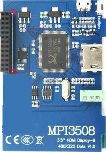
The MPI3508 comes in a 32-pin QFN package. Below is the pin configuration:

Pin Number Pin Name Description
1 VDD Power supply (1.8V to 3.6V)
2 GND Ground
3 GPIO0 General-purpose I/O
4 GPIO1 General-purpose I/O
5 ADC_IN0 Analog input channel 0
6 ADC_IN1 Analog input channel 1
7 UART_TX UART transmit
8 UART_RX UART receive
9 SPI_MOSI SPI Master Out Slave In
10 SPI_MISO SPI Master In Slave Out
11 SPI_SCK SPI Clock
12 SPI_CS SPI Chip Select
13 I2C_SCL I2C Clock
14 I2C_SDA I2C Data
15-30 GPIO2-17 General-purpose I/O
31 RESET Reset input (active low)
32 NC Not connected

Usage Instructions

How to Use the MPI3508 in a Circuit

  1. Power Supply: Connect the VDD pin to a stable power source (1.8V to 3.6V) and the GND pin to ground.
  2. GPIO Configuration: Configure the GPIO pins as input or output based on your application. Unused GPIO pins should be left floating or pulled to ground through a resistor.
  3. Communication Protocols: Use the appropriate pins for I2C, SPI, or UART communication. Ensure proper pull-up resistors for I2C lines.
  4. ADC Usage: Connect analog sensors to the ADC_IN pins. Ensure the input voltage does not exceed the operating voltage range.
  5. Reset: Use the RESET pin to initialize the microcontroller. This pin is active low.

Important Considerations and Best Practices

  • Decoupling Capacitors: Place a 0.1 µF ceramic capacitor close to the VDD pin to reduce noise and stabilize the power supply.
  • Clock Source: If an external clock is required, connect it to the appropriate GPIO pin configured as a clock input.
  • Programming: Use an appropriate programmer or development board to upload firmware to the microcontroller.
  • ESD Protection: Add ESD protection diodes to sensitive pins in environments prone to electrostatic discharge.

Example: Connecting the MPI3508 to an Arduino UNO

The MPI3508 can be interfaced with an Arduino UNO via I2C. Below is an example code snippet:

#include <Wire.h> // Include the Wire library for I2C communication

#define MPI3508_ADDRESS 0x48 // Replace with the actual I2C address of the MPI3508

void setup() {
  Wire.begin(); // Initialize I2C communication
  Serial.begin(9600); // Initialize serial communication for debugging

  // Send a test command to the MPI3508
  Wire.beginTransmission(MPI3508_ADDRESS);
  Wire.write(0x01); // Example command
  Wire.endTransmission();

  Serial.println("MPI3508 initialized.");
}

void loop() {
  Wire.requestFrom(MPI3508_ADDRESS, 2); // Request 2 bytes of data from the MPI3508

  if (Wire.available() == 2) {
    int data = Wire.read() << 8 | Wire.read(); // Combine two bytes into a single value
    Serial.print("Received data: ");
    Serial.println(data);
  }

  delay(1000); // Wait for 1 second before the next request
}

Notes:

  • Replace MPI3508_ADDRESS with the actual I2C address of your device.
  • Ensure proper pull-up resistors (typically 4.7 kΩ) are connected to the I2C lines.

Troubleshooting and FAQs

Common Issues and Solutions

  1. Microcontroller Not Powering On

    • Cause: Incorrect power supply voltage or missing decoupling capacitor.
    • Solution: Verify the power supply voltage is within the 1.8V to 3.6V range. Add a 0.1 µF capacitor near the VDD pin.
  2. No Communication via I2C/SPI/UART

    • Cause: Incorrect wiring or configuration.
    • Solution: Double-check the connections and ensure the correct pins are used. Verify the communication settings (e.g., baud rate, clock speed).
  3. ADC Readings Are Inaccurate

    • Cause: Noise or incorrect input voltage.
    • Solution: Ensure the input voltage is within the ADC range. Add a low-pass filter to reduce noise.
  4. Microcontroller Not Responding

    • Cause: Firmware issue or incorrect reset configuration.
    • Solution: Reprogram the microcontroller and verify the RESET pin is properly connected.

FAQs

Q: Can the MPI3508 operate at 5V?
A: No, the MPI3508 operates within a voltage range of 1.8V to 3.6V. Exceeding this range may damage the device.

Q: How many ADC channels are available?
A: The MPI3508 has two 12-bit ADC channels (ADC_IN0 and ADC_IN1).

Q: Is the MPI3508 compatible with 3.3V logic?
A: Yes, the MPI3508 is fully compatible with 3.3V logic levels.

Q: Can I use the GPIO pins for PWM output?
A: Yes, some GPIO pins can be configured for PWM output. Refer to the datasheet for details on PWM-capable pins.