How to Use RTC DS1032: Examples, Pinouts, and Specs
Introduction
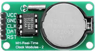
The DS1032, manufactured by ENGLAB (Part ID: DS1302), is a real-time clock (RTC) module designed to keep track of the current time and date. It is equipped with a low-power design, making it ideal for battery-operated devices. The DS1032 communicates with microcontrollers via a simple serial interface, ensuring seamless integration into a variety of applications.
Explore Projects Built with RTC DS1032


Explore Projects Built with RTC DS1032
Common Applications
- Digital clocks and timers
- Data loggers
- Home automation systems
- Embedded systems requiring timekeeping
- Battery-powered devices
Technical Specifications
The DS1032 offers robust performance and flexibility for timekeeping applications. Below are its key technical specifications:
| Parameter | Value |
|---|---|
| Operating Voltage | 2.0V to 5.5V |
| Operating Current | 300 nA (typical at 2.0V) |
| Timekeeping Accuracy | ±2 minutes per month (at 25°C) |
| Communication Protocol | Serial (3-wire interface) |
| Clock Format | 24-hour or 12-hour with AM/PM |
| Backup Battery Support | Yes |
| Temperature Range | -40°C to +85°C |
Pin Configuration and Descriptions
The DS1032 has an 8-pin configuration. Below is the pinout and description:
| Pin | Name | Description |
|---|---|---|
| 1 | VCC | Main power supply (2.0V to 5.5V). |
| 2 | GND | Ground connection. |
| 3 | CE | Chip Enable: Activates the device for communication. |
| 4 | I/O | Data Input/Output: Used for serial data transfer. |
| 5 | SCLK | Serial Clock: Synchronizes data transfer between the DS1032 and microcontroller. |
| 6 | VBAT | Backup Battery Input: Connect to a battery for timekeeping during power loss. |
| 7 | NC | No Connection: Leave unconnected. |
| 8 | NC | No Connection: Leave unconnected. |
Usage Instructions
The DS1032 is straightforward to use in a circuit. Follow the steps below to integrate it into your project:
Circuit Connection
- Connect the VCC pin to the power supply (2.0V to 5.5V).
- Connect the GND pin to the ground of your circuit.
- Connect the CE, I/O, and SCLK pins to the corresponding pins on your microcontroller.
- If backup timekeeping is required during power loss, connect a 3V coin cell battery to the VBAT pin.
Important Considerations
- Use pull-up resistors (typically 10kΩ) on the I/O and SCLK lines for reliable communication.
- Ensure the backup battery voltage is within the specified range (typically 3V).
- Avoid leaving the CE pin active for extended periods to minimize power consumption.
Example Code for Arduino UNO
Below is an example of how to interface the DS1032 with an Arduino UNO to read the current time:
#include <DS1302.h> // Include the DS1302 library

// Define the DS1032 pins connected to the Arduino
#define CE_PIN 7    // Chip Enable pin
#define IO_PIN 6    // Data Input/Output pin
#define SCLK_PIN 5  // Serial Clock pin

// Create an instance of the DS1302 class
DS1302 rtc(CE_PIN, IO_PIN, SCLK_PIN);

void setup() {
  Serial.begin(9600); // Initialize serial communication
  rtc.halt(false);    // Start the RTC
  rtc.writeProtect(false); // Disable write protection

  // Set the current date and time (YYYY, MM, DD, HH, MM, SS)
  rtc.setDateTime(2023, 10, 15, 14, 30, 0); // Example: October 15, 2023, 14:30:00
}

void loop() {
  // Read the current date and time
  DS1302::DateTime now = rtc.getDateTime();

  // Print the date and time to the Serial Monitor
  Serial.print("Date: ");
  Serial.print(now.year); Serial.print("-");
  Serial.print(now.month); Serial.print("-");
  Serial.println(now.day);

  Serial.print("Time: ");
  Serial.print(now.hour); Serial.print(":");
  Serial.print(now.minute); Serial.print(":");
  Serial.println(now.second);

  delay(1000); // Wait for 1 second before updating
}
Best Practices
- Always verify the connections before powering the circuit to avoid damage.
- Use decoupling capacitors (e.g., 0.1µF) near the VCC pin to stabilize the power supply.
- Regularly check the backup battery voltage to ensure uninterrupted timekeeping.
Troubleshooting and FAQs
Common Issues and Solutions
RTC not responding to commands:
- Verify the connections, especially the CE, I/O, and SCLK pins.
- Ensure the microcontroller's logic level matches the DS1032's operating voltage.
Incorrect time or date:
- Check if the backup battery is properly connected and has sufficient charge.
- Ensure the RTC is initialized with the correct date and time.
High power consumption:
- Confirm that the CE pin is not left active unnecessarily.
- Use a low-leakage backup battery to minimize power drain.
Communication errors:
- Use pull-up resistors on the I/O and SCLK lines.
- Ensure the serial clock frequency is within the supported range.
FAQs
Q: Can the DS1032 operate without a backup battery?
A: Yes, but it will lose the current time and date when the main power supply is disconnected.
Q: What is the maximum clock frequency for the serial interface?
A: The DS1032 supports a maximum clock frequency of 2 MHz for the serial interface.
Q: How long does the backup battery last?
A: The battery life depends on its capacity and the DS1032's low power consumption (300 nA typical). A standard CR2032 coin cell can last several years.
Q: Can I use the DS1032 with a 3.3V microcontroller?
A: Yes, the DS1032 operates within a voltage range of 2.0V to 5.5V, making it compatible with 3.3V systems.
By following this documentation, you can effectively integrate the DS1032 into your projects and troubleshoot any issues that arise.