Cirkit Designer Logo
Cirkit Designer
Your all-in-one circuit design IDE
Home / 
Component Documentation

How to Use LCD My: Examples, Pinouts, and Specs

Image of LCD My
Cirkit Designer LogoDesign with LCD My in Cirkit Designer

Introduction

The LCD My is a Liquid Crystal Display (LCD) module designed for displaying text and graphics in electronic devices. It is widely used in embedded systems, DIY electronics projects, and industrial applications due to its simplicity and versatility. The module often features a backlight, making it suitable for use in low-light environments. LCD My is ideal for projects requiring a user interface or visual feedback, such as temperature monitors, clocks, and IoT devices.

Explore Projects Built with LCD My

Use Cirkit Designer to design, explore, and prototype these projects online. Some projects support real-time simulation. Click "Open Project" to start designing instantly!
Arduino Leonardo Controlled I2C LCD Display for Text Scrolling
Image of final year project: A project utilizing LCD My in a practical application
This circuit features an Arduino Leonardo microcontroller connected to a 16x2 I2C LCD screen, powered by a 5V battery. The Arduino is programmed to display and continuously scroll a message on the LCD. The I2C communication protocol is used for the microcontroller to interface with the LCD, utilizing the SDA and SCL connections for data transfer.
Cirkit Designer LogoOpen Project in Cirkit Designer
Arduino Leonardo Controlled LCD Display with I2C Interface
Image of ert: A project utilizing LCD My in a practical application
This circuit connects an Arduino Leonardo microcontroller to a 16x2 LCD display via an LCM1602 IIC interface module, enabling the display of text on the LCD. The Arduino is programmed to display the messages 'TEST LCD i2C' and 'KelasRobot.com' on the LCD. The IIC module facilitates communication between the Arduino and the LCD using the I2C protocol, simplifying the wiring and pin usage.
Cirkit Designer LogoOpen Project in Cirkit Designer
Arduino Nano Controlled LCD Interface with Pushbutton Inputs
Image of MacroDisplay: A project utilizing LCD My in a practical application
This circuit features a Nano 3.0 ATmega328P microcontroller connected to a 16x2 I2C LCD display for output. Two pushbuttons, each with a 10k Ohm pull-down resistor, are connected to digital pins D2 and D3 of the microcontroller for input. The LCD and pushbuttons are powered by the 5V output from the microcontroller, and all components share a common ground.
Cirkit Designer LogoOpen Project in Cirkit Designer
Arduino Nano and I2C LCD Display Power Supply Project
Image of lcd display: A project utilizing LCD My in a practical application
This circuit features an Arduino Nano microcontroller interfaced with a 20x4 I2C LCD panel for display purposes. The LCD panel is powered by a 5V AC-DC power supply unit, and the Arduino Nano communicates with the LCD via I2C protocol using its A5 (SDA) and A1 (SCL) pins.
Cirkit Designer LogoOpen Project in Cirkit Designer

Explore Projects Built with LCD My

Use Cirkit Designer to design, explore, and prototype these projects online. Some projects support real-time simulation. Click "Open Project" to start designing instantly!
Image of final year project: A project utilizing LCD My in a practical application
Arduino Leonardo Controlled I2C LCD Display for Text Scrolling
This circuit features an Arduino Leonardo microcontroller connected to a 16x2 I2C LCD screen, powered by a 5V battery. The Arduino is programmed to display and continuously scroll a message on the LCD. The I2C communication protocol is used for the microcontroller to interface with the LCD, utilizing the SDA and SCL connections for data transfer.
Cirkit Designer LogoOpen Project in Cirkit Designer
Image of ert: A project utilizing LCD My in a practical application
Arduino Leonardo Controlled LCD Display with I2C Interface
This circuit connects an Arduino Leonardo microcontroller to a 16x2 LCD display via an LCM1602 IIC interface module, enabling the display of text on the LCD. The Arduino is programmed to display the messages 'TEST LCD i2C' and 'KelasRobot.com' on the LCD. The IIC module facilitates communication between the Arduino and the LCD using the I2C protocol, simplifying the wiring and pin usage.
Cirkit Designer LogoOpen Project in Cirkit Designer
Image of MacroDisplay: A project utilizing LCD My in a practical application
Arduino Nano Controlled LCD Interface with Pushbutton Inputs
This circuit features a Nano 3.0 ATmega328P microcontroller connected to a 16x2 I2C LCD display for output. Two pushbuttons, each with a 10k Ohm pull-down resistor, are connected to digital pins D2 and D3 of the microcontroller for input. The LCD and pushbuttons are powered by the 5V output from the microcontroller, and all components share a common ground.
Cirkit Designer LogoOpen Project in Cirkit Designer
Image of lcd display: A project utilizing LCD My in a practical application
Arduino Nano and I2C LCD Display Power Supply Project
This circuit features an Arduino Nano microcontroller interfaced with a 20x4 I2C LCD panel for display purposes. The LCD panel is powered by a 5V AC-DC power supply unit, and the Arduino Nano communicates with the LCD via I2C protocol using its A5 (SDA) and A1 (SCL) pins.
Cirkit Designer LogoOpen Project in Cirkit Designer

Technical Specifications

  • Display Type: Liquid Crystal Display (LCD)
  • Character Support: 16x2 (16 characters per line, 2 lines) or 20x4 (20 characters per line, 4 lines) depending on the model
  • Operating Voltage: 4.7V to 5.3V
  • Current Consumption: 1mA (without backlight), 15mA to 25mA (with backlight)
  • Interface: Parallel (4-bit or 8-bit mode)
  • Backlight: LED (optional, controllable via a pin)
  • Operating Temperature: -20°C to 70°C
  • Dimensions: Varies by model (e.g., 80mm x 36mm for 16x2)

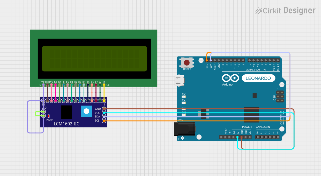
Pin Configuration and Descriptions

The LCD My module typically has 16 pins. Below is the pin configuration:

Pin Number Name Description
1 VSS Ground (0V) connection
2 VDD Power supply (4.7V to 5.3V)
3 VO Contrast adjustment (connect to a potentiometer for contrast control)
4 RS Register Select (0: Command mode, 1: Data mode)
5 RW Read/Write (0: Write to LCD, 1: Read from LCD)
6 E Enable pin (triggers data read/write when toggled)
7-14 D0-D7 Data pins (used for 4-bit or 8-bit communication)
15 LED+ Backlight anode (connect to +5V via a resistor if backlight is used)
16 LED- Backlight cathode (connect to ground if backlight is used)

Usage Instructions

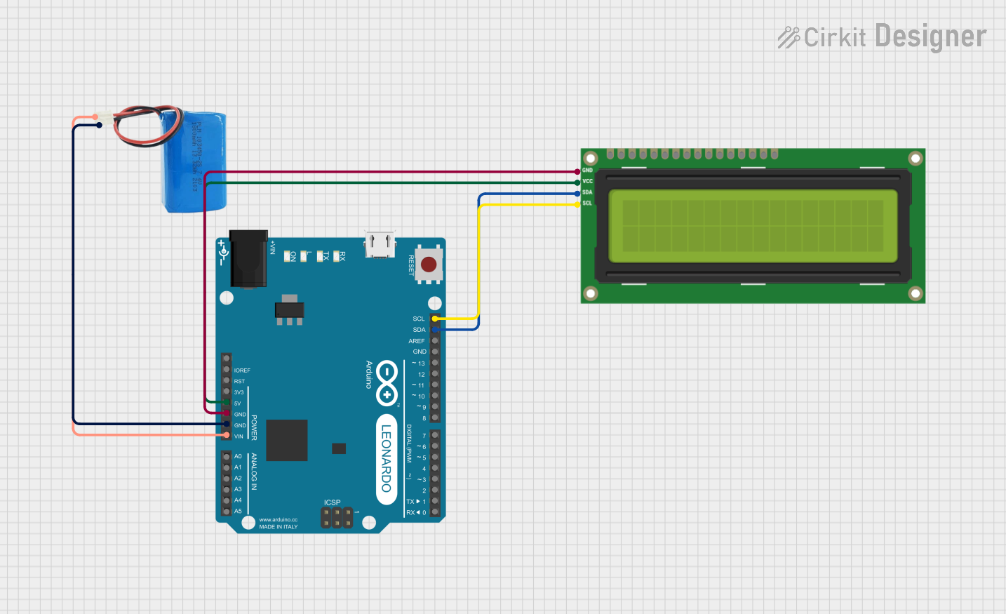
Connecting the LCD My to an Arduino UNO

The LCD My module can be easily interfaced with an Arduino UNO using the 4-bit mode to save pins. Below is a step-by-step guide:

  1. Wiring:

    • Connect VSS to GND and VDD to 5V on the Arduino.
    • Connect VO to the middle pin of a 10kΩ potentiometer. Connect the other two potentiometer pins to 5V and GND.
    • Connect RS to Arduino digital pin 12.
    • Connect RW to GND (write mode).
    • Connect E to Arduino digital pin 11.
    • Connect D4, D5, D6, and D7 to Arduino digital pins 5, 4, 3, and 2, respectively.
    • If using the backlight, connect LED+ to 5V via a 220Ω resistor and LED- to GND.
  2. Arduino Code: Use the LiquidCrystal library to control the LCD. Below is an example code snippet:

    // Include the LiquidCrystal library
    #include <LiquidCrystal.h>
    
    // Initialize the library with the pins connected to the LCD
    LiquidCrystal lcd(12, 11, 5, 4, 3, 2);
    
    void setup() {
      // Set up the LCD's number of columns and rows
      lcd.begin(16, 2);
    
      // Print a message to the LCD
      lcd.print("Hello, World!");
    }
    
    void loop() {
      // Move the cursor to the second line, first column
      lcd.setCursor(0, 1);
    
      // Print a dynamic message
      lcd.print(millis() / 1000); // Display elapsed time in seconds
    }
    

Important Considerations

  • Contrast Adjustment: Use a 10kΩ potentiometer to adjust the contrast for optimal visibility.
  • Backlight Control: If the backlight is not needed, leave the LED+ and LED- pins unconnected to save power.
  • Data Mode: Use 4-bit mode for simpler wiring and to save Arduino pins. Use 8-bit mode only if required for faster data transfer.
  • Power Supply: Ensure a stable 5V power supply to avoid flickering or malfunction.

Troubleshooting and FAQs

Common Issues

  1. No Display on the Screen:

    • Check the power connections (VSS to GND, VDD to 5V).
    • Adjust the contrast using the potentiometer connected to VO.
    • Verify the backlight connections if the screen is too dim.
  2. Random Characters or No Response:

    • Ensure the RS, RW, and E pins are correctly connected to the Arduino.
    • Verify the data pins (D4-D7 in 4-bit mode) are properly wired.
    • Check the code for correct pin assignments in the LiquidCrystal initialization.
  3. Flickering or Unstable Display:

    • Use a decoupling capacitor (e.g., 0.1µF) across the power supply pins to stabilize voltage.
    • Ensure the power supply can provide sufficient current for the LCD and backlight.

FAQs

Q: Can I use the LCD My with a 3.3V microcontroller?
A: The LCD My is designed for 5V operation. To use it with a 3.3V microcontroller, you will need a level shifter or voltage divider for the data lines.

Q: How do I display custom characters?
A: Use the createChar() function in the LiquidCrystal library to define and display custom characters.

Q: Can I control the backlight brightness?
A: Yes, connect the LED+ pin to a PWM-capable pin on the microcontroller and use PWM to adjust brightness.

By following this documentation, you can effectively integrate the LCD My module into your projects and troubleshoot common issues with ease.