How to Use ESP32-S3-WROOM-1 FRONT: Examples, Pinouts, and Specs
Introduction
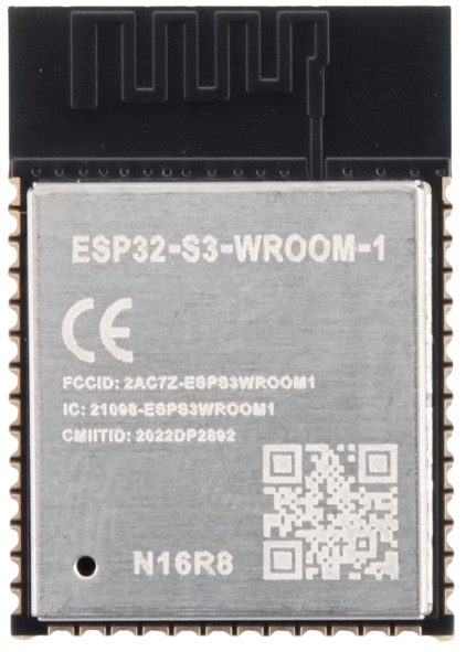
The ESP32-S3-WROOM-1 FRONT is a powerful Wi-Fi and Bluetooth microcontroller module designed for Internet of Things (IoT) applications. It features dual-core processing, integrated peripherals, and support for various connectivity options, making it ideal for a wide range of smart devices and embedded systems. This module is built for high performance, low power consumption, and ease of integration into IoT projects.
Explore Projects Built with ESP32-S3-WROOM-1 FRONT


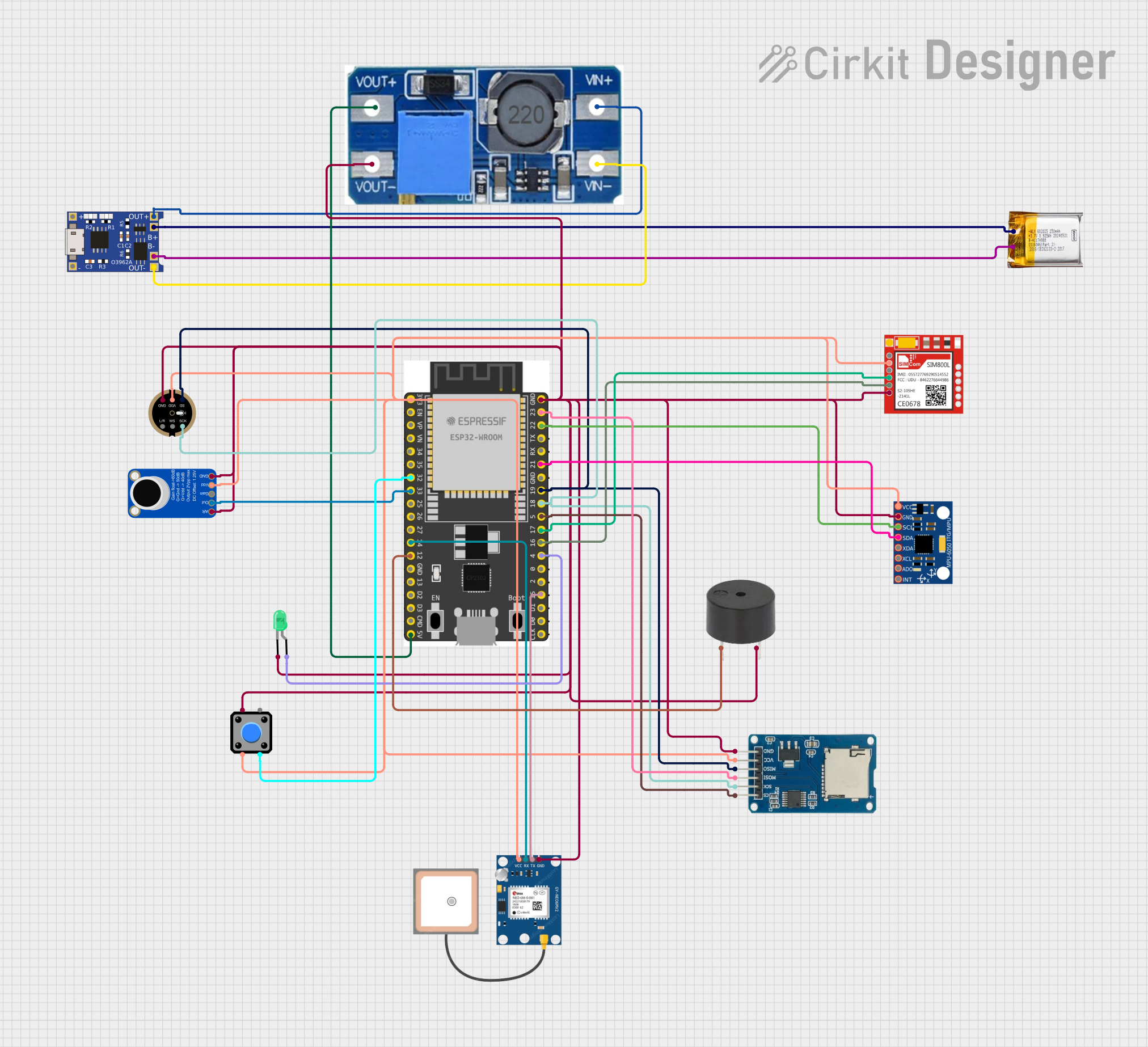
Explore Projects Built with ESP32-S3-WROOM-1 FRONT
Common Applications and Use Cases
- Smart home devices (e.g., smart lights, thermostats, and security systems)
- Wearable technology
- Industrial IoT (IIoT) applications
- Wireless sensor networks
- Robotics and automation
- Edge computing and AI/ML applications
Technical Specifications
Key Technical Details
| Parameter | Specification |
|---|---|
| Microcontroller | ESP32-S3 (Xtensa® 32-bit LX7 dual-core processor) |
| Clock Speed | Up to 240 MHz |
| Wireless Connectivity | Wi-Fi 802.11 b/g/n (2.4 GHz), Bluetooth 5.0 |
| Flash Memory | 4 MB (default) |
| SRAM | 512 KB |
| GPIO Pins | Up to 45 (multiplexed with other functions) |
| Operating Voltage | 3.0V to 3.6V |
| Power Consumption | Ultra-low power in deep sleep mode (~10 µA) |
| Interfaces | SPI, I2C, I2S, UART, ADC, DAC, PWM, USB-OTG |
| Dimensions | 18 mm x 19.2 mm |
| Operating Temperature Range | -40°C to +85°C |
Pin Configuration and Descriptions
The ESP32-S3-WROOM-1 FRONT module has multiple pins with versatile functionality. Below is a table of the most commonly used pins:
| Pin Number | Pin Name | Functionality |
|---|---|---|
| 1 | GND | Ground pin |
| 2 | 3V3 | Power supply (3.3V) |
| 3 | EN | Enable pin (active high, resets the module) |
| 4 | GPIO0 | General-purpose I/O, boot mode selection |
| 5 | GPIO1 | General-purpose I/O, UART TX |
| 6 | GPIO2 | General-purpose I/O, UART RX |
| 7 | GPIO12 | General-purpose I/O, ADC2 channel |
| 8 | GPIO13 | General-purpose I/O, PWM output |
| 9 | GPIO14 | General-purpose I/O, SPI CLK |
| 10 | GPIO15 | General-purpose I/O, SPI MOSI |
Note: Many GPIO pins are multiplexed with other functions. Refer to the ESP32-S3 datasheet for a complete pinout and alternate functions.
Usage Instructions
How to Use the ESP32-S3-WROOM-1 FRONT in a Circuit
- Power Supply: Connect the
3V3pin to a stable 3.3V power source and theGNDpin to ground. - Boot Mode: To enter bootloader mode for programming, connect
GPIO0to ground during reset. - Programming: Use a USB-to-UART converter to connect the module to your computer. Connect
TXandRXpins to the converter, and use tools like the ESP-IDF or Arduino IDE for programming. - Peripherals: Connect sensors, actuators, or other peripherals to the GPIO pins. Ensure the voltage levels are compatible with the module.
Important Considerations and Best Practices
- Power Supply: Use a low-noise, stable 3.3V power source to avoid performance issues.
- GPIO Voltage Levels: All GPIO pins are 3.3V logic. Avoid applying 5V directly to any pin.
- Antenna Placement: Ensure the onboard antenna has sufficient clearance from metal objects to avoid interference.
- Deep Sleep Mode: Use deep sleep mode to minimize power consumption in battery-powered applications.
- Firmware Updates: Regularly update the firmware to benefit from the latest features and security patches.
Example: Connecting to an Arduino UNO
The ESP32-S3-WROOM-1 FRONT can be programmed using the Arduino IDE. Below is an example code snippet to connect the module to a Wi-Fi network:
#include <WiFi.h> // Include the Wi-Fi library for ESP32

// Replace with your network credentials
const char* ssid = "Your_SSID";
const char* password = "Your_PASSWORD";

void setup() {
  Serial.begin(115200); // Initialize serial communication at 115200 baud
  delay(1000); // Wait for a second to stabilize

  Serial.println("Connecting to Wi-Fi...");
  WiFi.begin(ssid, password); // Start Wi-Fi connection

  while (WiFi.status() != WL_CONNECTED) {
    delay(500); // Wait for connection
    Serial.print(".");
  }

  Serial.println("\nWi-Fi connected!");
  Serial.print("IP Address: ");
  Serial.println(WiFi.localIP()); // Print the assigned IP address
}

void loop() {
  // Add your main code here
}
Note: Ensure the ESP32-S3-WROOM-1 FRONT is in programming mode when uploading the code.
Troubleshooting and FAQs
Common Issues and Solutions
Module Not Responding
- Cause: Incorrect power supply or wiring.
- Solution: Verify the power supply voltage (3.3V) and check all connections.
Wi-Fi Connection Fails
- Cause: Incorrect SSID or password.
- Solution: Double-check the credentials in your code. Ensure the Wi-Fi network is operational.
GPIO Pin Not Working
- Cause: Pin conflict or incorrect configuration.
- Solution: Check if the pin is multiplexed with another function. Configure it properly in your code.
Programming Fails
- Cause: Incorrect boot mode or driver issues.
- Solution: Ensure
GPIO0is grounded during reset. Install the correct USB-to-UART drivers.
FAQs
Q: Can I use 5V peripherals with the ESP32-S3-WROOM-1 FRONT?
A: No, the module operates at 3.3V logic. Use level shifters for 5V peripherals.Q: How do I update the firmware?
A: Use the ESP-IDF or Arduino IDE to flash the latest firmware via the USB-to-UART interface.Q: What is the maximum Wi-Fi range?
A: The range depends on the environment but typically extends up to 100 meters in open space.Q: Can I use the module for Bluetooth audio streaming?
A: Yes, the ESP32-S3 supports Bluetooth 5.0, which includes audio streaming capabilities.
By following this documentation, you can effectively integrate the ESP32-S3-WROOM-1 FRONT into your IoT projects.