How to Use 4x3 Keypad: Examples, Pinouts, and Specs
Introduction
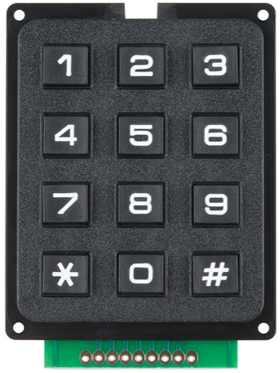
A 4x3 keypad is a matrix keypad consisting of 4 rows and 3 columns, typically used for user input in electronic devices. It allows users to input numerical or alphanumeric data by pressing the keys, which are arranged in a grid format. This component is widely used in applications such as security systems, calculators, and embedded systems where user interaction is required.
Explore Projects Built with 4x3 Keypad


Explore Projects Built with 4x3 Keypad
Common Applications and Use Cases
- Security systems (e.g., PIN entry for door locks)
- Calculators and handheld devices
- Menu navigation in embedded systems
- Home automation systems
- Industrial control panels
Technical Specifications
The 4x3 keypad is a passive component that requires external circuitry or a microcontroller to function. Below are its key technical details:
Key Technical Details
- Number of Keys: 12 (4 rows × 3 columns)
- Operating Voltage: 3.3V to 5V
- Current Consumption: Minimal (depends on pull-up resistors or microcontroller input)
- Keypad Dimensions: Varies by manufacturer (commonly ~70mm × 50mm)
- Interface: 7-pin matrix (4 row pins, 3 column pins)
- Material: Plastic or rubber keys with conductive pads
Pin Configuration and Descriptions
The 4x3 keypad has 7 pins, which correspond to the rows and columns of the matrix. The pinout may vary slightly depending on the manufacturer, but the general configuration is as follows:
| Pin | Name | Description |
|---|---|---|
| 1 | R1 | Row 1 |
| 2 | R2 | Row 2 |
| 3 | R3 | Row 3 |
| 4 | R4 | Row 4 |
| 5 | C1 | Column 1 |
| 6 | C2 | Column 2 |
| 7 | C3 | Column 3 |
Usage Instructions
How to Use the 4x3 Keypad in a Circuit
Connect the Keypad to a Microcontroller:
- Connect the 4 row pins (R1–R4) and 3 column pins (C1–C3) to the GPIO pins of a microcontroller.
- Use pull-up or pull-down resistors if required by the microcontroller's input configuration.
Scan the Keypad Matrix:
- The microcontroller sends signals to the rows and reads the columns to detect which key is pressed.
- A key press is identified by detecting a connection between a specific row and column.
Debounce the Keys:
- Implement software or hardware debouncing to avoid false keypress detection caused by mechanical bouncing.
Power Requirements:
- Ensure the keypad operates within its voltage range (3.3V–5V). Most microcontrollers can directly interface with the keypad.
Important Considerations and Best Practices
- Debouncing: Use a software debounce algorithm or a capacitor to stabilize keypress signals.
- Pin Mapping: Verify the pinout of your specific keypad model, as it may differ slightly.
- Pull-Up Resistors: Some microcontrollers require external pull-up resistors for proper operation.
- Keypad Library: Use a keypad library (e.g., Arduino Keypad Library) to simplify matrix scanning and key detection.
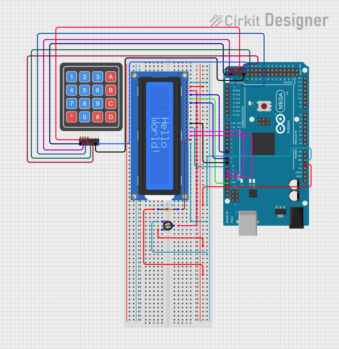
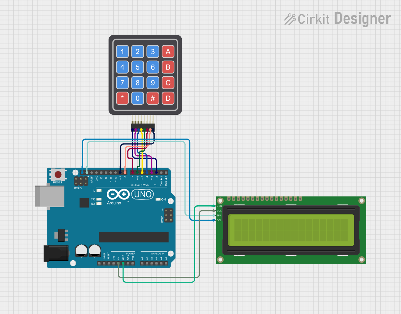
Example: Using a 4x3 Keypad with Arduino UNO
Below is an example of how to connect and use a 4x3 keypad with an Arduino UNO:
Circuit Connections
- Connect the 4 row pins (R1–R4) to Arduino digital pins 9, 8, 7, and 6.
- Connect the 3 column pins (C1–C3) to Arduino digital pins 5, 4, and 3.
- No external resistors are needed if the Arduino's internal pull-up resistors are enabled.
Arduino Code Example
#include <Keypad.h>

// Define the rows and columns of the keypad
const byte ROWS = 4; // Four rows
const byte COLS = 3; // Three columns

// Define the keymap for the 4x3 keypad
char keys[ROWS][COLS] = {
  {'1', '2', '3'},
  {'4', '5', '6'},
  {'7', '8', '9'},
  {'*', '0', '#'}
};

// Define the row and column pins connected to the Arduino
byte rowPins[ROWS] = {9, 8, 7, 6}; // Connect to R1, R2, R3, R4
byte colPins[COLS] = {5, 4, 3};    // Connect to C1, C2, C3

// Create a Keypad object
Keypad keypad = Keypad(makeKeymap(keys), rowPins, colPins, ROWS, COLS);

void setup() {
  Serial.begin(9600); // Initialize serial communication
  Serial.println("4x3 Keypad Test");
}

void loop() {
  char key = keypad.getKey(); // Get the key pressed

  if (key) {
    // If a key is pressed, print it to the Serial Monitor
    Serial.print("Key Pressed: ");
    Serial.println(key);
  }
}
Notes on the Code
- The
Keypadlibrary simplifies the process of scanning the matrix and detecting keypresses. - The
getKey()function returns the character of the pressed key orNULLif no key is pressed. - Ensure the
Keypadlibrary is installed in your Arduino IDE.
Troubleshooting and FAQs
Common Issues and Solutions
No Keypress Detected:
- Verify the wiring between the keypad and the microcontroller.
- Check if the correct pins are defined in the code.
Multiple Keys Detected:
- Ensure proper debouncing is implemented in the code.
- Check for short circuits between row and column pins.
Incorrect Key Mapping:
- Verify the keymap in the code matches the physical layout of the keypad.
- Double-check the pin connections and update the
rowPinsandcolPinsarrays if needed.
Keypad Not Responding:
- Ensure the keypad is powered within its operating voltage range.
- Test the keypad with a multimeter to confirm continuity when keys are pressed.
FAQs
Q: Can I use a 4x3 keypad with a 3.3V microcontroller?
A: Yes, the keypad is compatible with 3.3V systems. Ensure the microcontroller's GPIO pins can detect the voltage levels.
Q: How do I extend the keypad's cable length?
A: Use shielded cables to reduce noise and interference. Keep the length as short as possible for reliable operation.
Q: Can I use the keypad for alphanumeric input?
A: Yes, you can map the keys to alphanumeric characters in the code, but the physical keypad layout will remain fixed.
Q: Is the keypad waterproof?
A: Most 4x3 keypads are not waterproof. Use a protective enclosure for outdoor or wet environments.