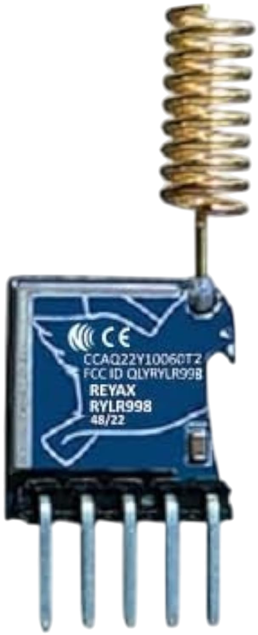
How to Use RLYR998: Examples, Pinouts, and Specs
Introduction
The RLYR998 is a versatile relay module designed for switching applications. It enables users to control high-voltage devices, such as motors, lights, and appliances, using low-voltage control signals. This makes it an essential component in automation, home control systems, and industrial applications. The RLYR998 typically features multiple channels, allowing simultaneous control of multiple devices, and is compatible with microcontrollers like Arduino, Raspberry Pi, and other logic-level control systems.
Explore Projects Built with RLYR998


Explore Projects Built with RLYR998
Common Applications
- Home automation (e.g., controlling lights, fans, or appliances)
- Industrial control systems
- Robotics and motor control
- IoT (Internet of Things) projects
- Security systems (e.g., activating alarms or locks)
Technical Specifications
The RLYR998 relay module is designed to handle a wide range of voltages and currents, making it suitable for various applications. Below are its key technical details:
General Specifications
- Operating Voltage (Input): 5V DC
- Relay Output Voltage: 250V AC / 30V DC (maximum)
- Relay Output Current: 10A (maximum)
- Trigger Voltage: 3.3V to 5V (logic-level compatible)
- Number of Channels: 2, 4, or 8 (depending on the model)
- Isolation: Optocoupler-based isolation for safe operation
- Indicator LEDs: Status LEDs for each channel
- Dimensions: Varies by model (e.g., 2-channel: 50mm x 40mm)
Pin Configuration and Descriptions
The RLYR998 module has input pins for control signals and output terminals for connecting high-voltage devices. Below is the pin configuration for a typical 4-channel RLYR998 module:
Input Pins
| Pin Name | Description |
|---|---|
| VCC | Power supply for the module (5V DC) |
| GND | Ground connection |
| IN1 | Control signal for Relay 1 (active LOW) |
| IN2 | Control signal for Relay 2 (active LOW) |
| IN3 | Control signal for Relay 3 (active LOW) |
| IN4 | Control signal for Relay 4 (active LOW) |
Output Terminals
| Terminal | Description |
|---|---|
| COM | Common terminal for the relay |
| NO | Normally Open terminal (default open) |
| NC | Normally Closed terminal (default closed) |
Each relay channel has its own set of COM, NO, and NC terminals.
Usage Instructions
How to Use the RLYR998 in a Circuit
- Power the Module:
- Connect the VCC pin to a 5V DC power source and the GND pin to ground.
- Connect Control Signals:
- Use digital output pins from a microcontroller (e.g., Arduino) to connect to the IN pins (IN1, IN2, etc.).
- The relay is triggered when the control signal is set to LOW.
- Connect the Load:
- Connect the high-voltage device to the relay's output terminals (COM, NO, NC) based on the desired switching configuration:
- Normally Open (NO): The circuit is open by default and closes when the relay is activated.
- Normally Closed (NC): The circuit is closed by default and opens when the relay is activated.
- Connect the high-voltage device to the relay's output terminals (COM, NO, NC) based on the desired switching configuration:
- Test the Circuit:
- Upload the control code to the microcontroller and test the relay's operation.
Important Considerations
- Ensure the load does not exceed the relay's maximum voltage and current ratings (250V AC / 30V DC, 10A).
- Use proper insulation and safety precautions when working with high-voltage devices.
- Avoid rapid switching of the relay to prevent wear and tear.
- Use a flyback diode across the relay coil if the module does not already include one, to protect the circuit from voltage spikes.
Example Code for Arduino UNO
Below is an example code snippet to control a 4-channel RLYR998 relay module using an Arduino UNO:
// Define relay control pins
#define RELAY1 2  // Relay 1 connected to digital pin 2
#define RELAY2 3  // Relay 2 connected to digital pin 3
#define RELAY3 4  // Relay 3 connected to digital pin 4
#define RELAY4 5  // Relay 4 connected to digital pin 5

void setup() {
  // Set relay pins as outputs
  pinMode(RELAY1, OUTPUT);
  pinMode(RELAY2, OUTPUT);
  pinMode(RELAY3, OUTPUT);
  pinMode(RELAY4, OUTPUT);

  // Initialize all relays to OFF (HIGH state for active LOW relays)
  digitalWrite(RELAY1, HIGH);
  digitalWrite(RELAY2, HIGH);
  digitalWrite(RELAY3, HIGH);
  digitalWrite(RELAY4, HIGH);
}

void loop() {
  // Example: Turn on Relay 1 and Relay 2 for 2 seconds
  digitalWrite(RELAY1, LOW);  // Activate Relay 1
  digitalWrite(RELAY2, LOW);  // Activate Relay 2
  delay(2000);                // Wait for 2 seconds

  // Turn off Relay 1 and Relay 2
  digitalWrite(RELAY1, HIGH); // Deactivate Relay 1
  digitalWrite(RELAY2, HIGH); // Deactivate Relay 2
  delay(2000);                // Wait for 2 seconds
}
Troubleshooting and FAQs
Common Issues and Solutions
Relay Not Activating:
- Cause: Insufficient power supply or incorrect wiring.
- Solution: Ensure the VCC pin is connected to a stable 5V DC source and the GND pin is properly grounded.
Relay Stuck in ON or OFF State:
- Cause: Faulty relay or incorrect control signal.
- Solution: Verify the control signal logic (active LOW) and check for damaged components.
Load Not Switching Properly:
- Cause: Exceeding the relay's voltage/current ratings or incorrect wiring.
- Solution: Ensure the load is within the relay's specifications and verify the wiring of the COM, NO, and NC terminals.
Interference with Microcontroller:
- Cause: Electromagnetic interference (EMI) from the relay.
- Solution: Use optocoupler isolation and keep high-voltage wiring separate from low-voltage control signals.
FAQs
Q: Can the RLYR998 be used with a 3.3V microcontroller?
A: Yes, the module is compatible with 3.3V logic levels, but ensure the VCC pin is still powered with 5V DC.Q: How many devices can I control with the RLYR998?
A: The number of devices depends on the number of channels in your module (e.g., 2, 4, or 8 channels).Q: Is the RLYR998 safe for high-voltage applications?
A: Yes, the module is designed for high-voltage applications, but always follow proper safety precautions and insulation practices.Q: Can I use the RLYR998 to control DC motors?
A: Yes, the relay can control DC motors as long as the motor's voltage and current are within the relay's specifications.