How to Use 3 Channel Line Follower: Examples, Pinouts, and Specs
Introduction
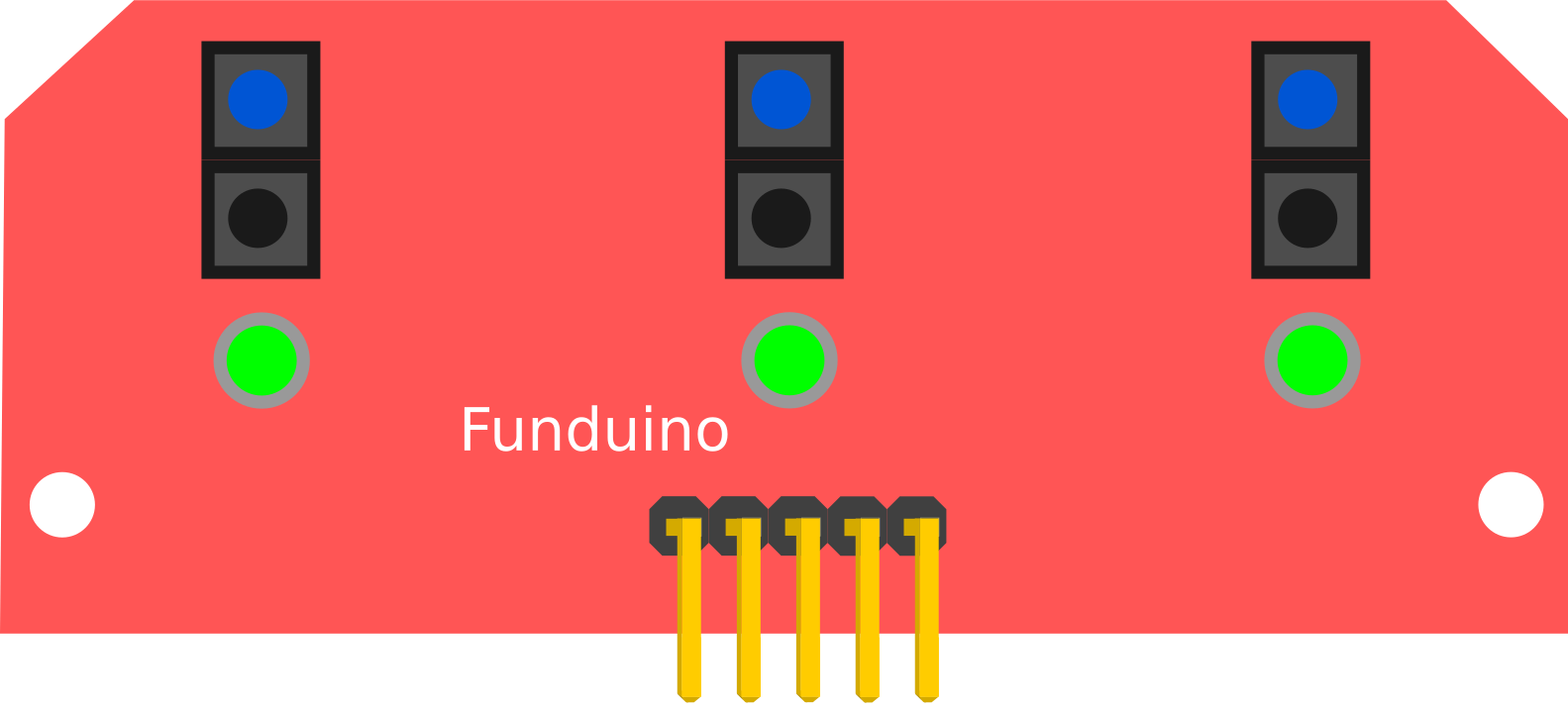
The 3 Channel Line Follower (manufactured by Vishay, part ID: TCTR5000) is a robotic sensor module designed to detect and follow lines on a surface. It uses three infrared (IR) sensors to differentiate between a line (typically black) and the surrounding background (typically white or lighter in color). This component is widely used in robotics for navigation, enabling robots to follow predefined paths with precision.
Explore Projects Built with 3 Channel Line Follower
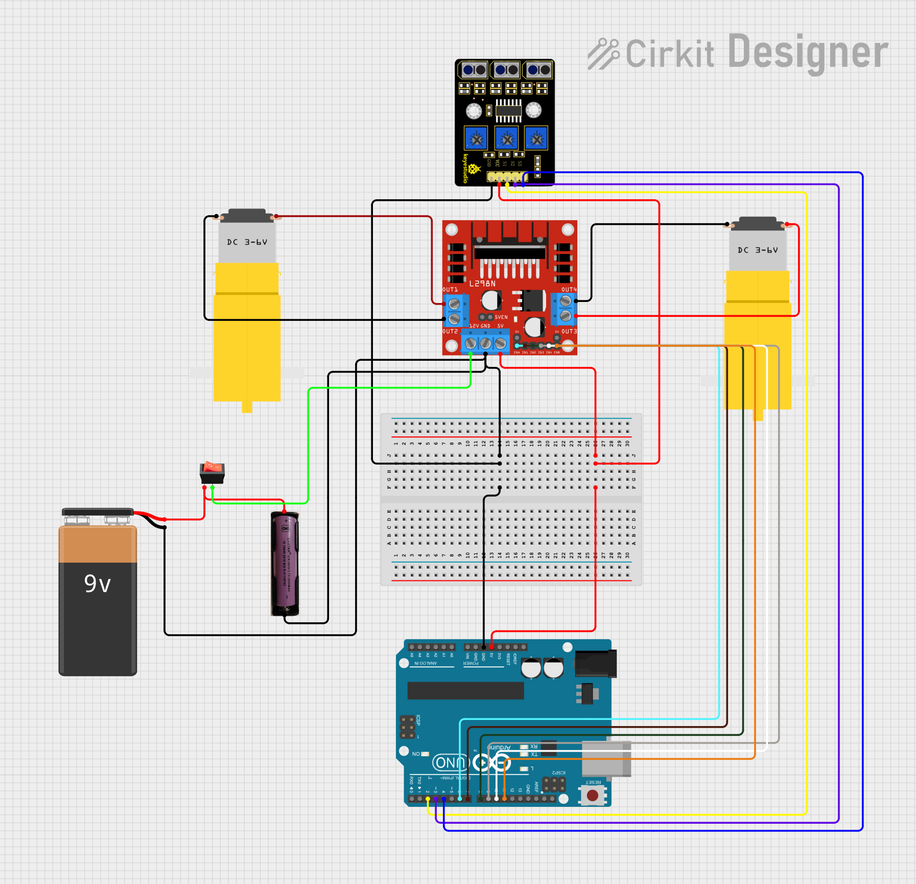
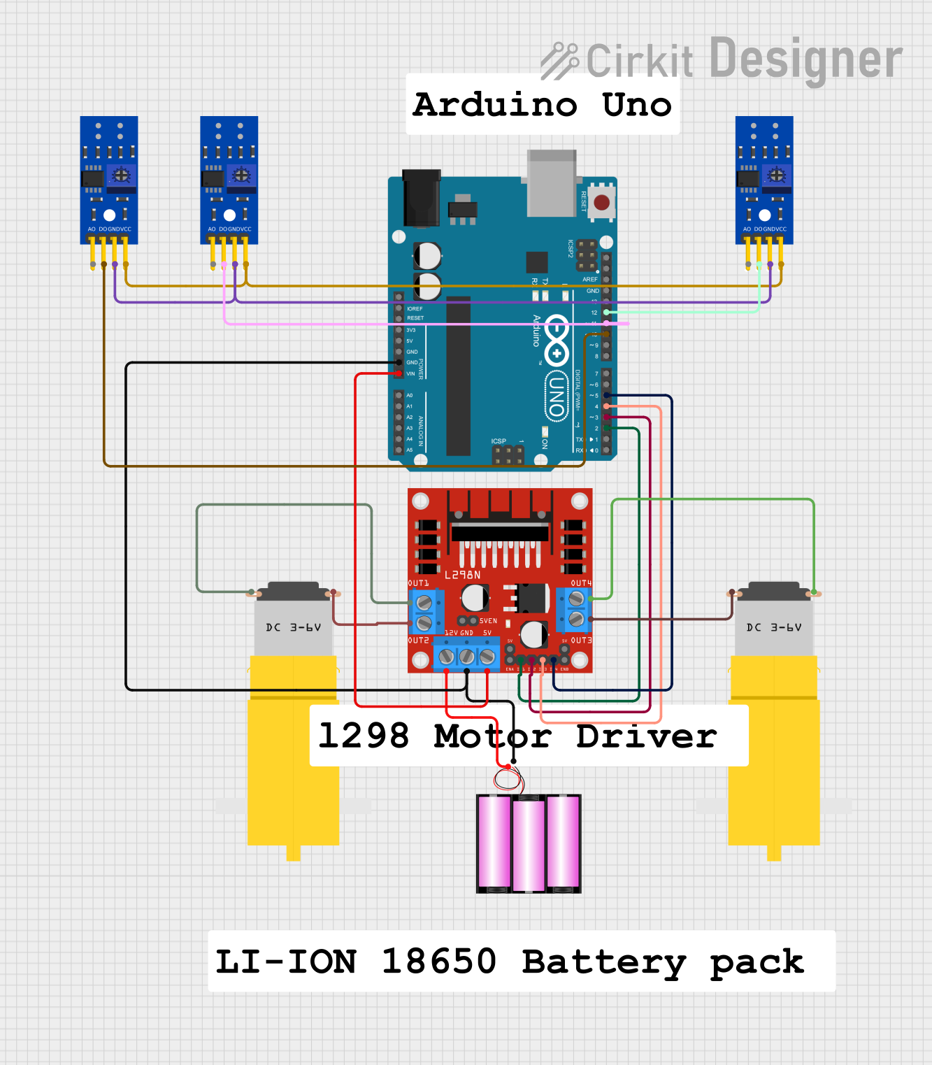
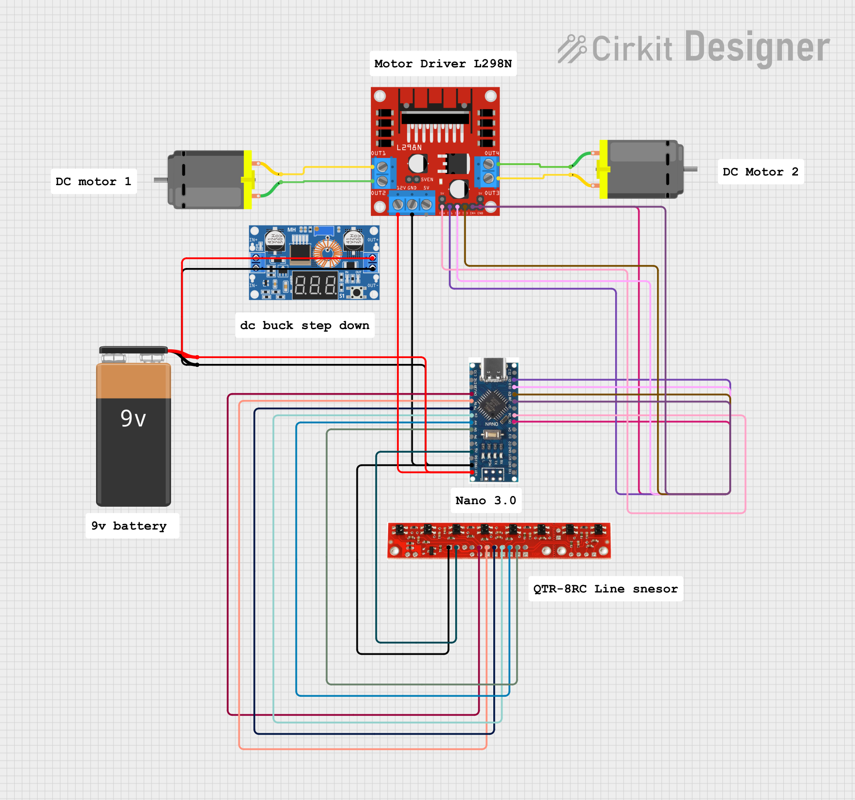
Explore Projects Built with 3 Channel Line Follower
Common Applications and Use Cases
- Line-following robots for educational and industrial purposes
- Automated guided vehicles (AGVs) in warehouses
- Obstacle avoidance and path correction systems
- Maze-solving robots
- DIY robotics projects
Technical Specifications
The TCTR5000-based 3 Channel Line Follower module has the following key specifications:
| Parameter | Value |
|---|---|
| Operating Voltage | 3.3V to 5V |
| Operating Current | ~20mA |
| Detection Range | 2mm to 10mm (optimal: 3mm-5mm) |
| Output Type | Digital (High/Low) |
| IR Wavelength | 950nm |
| Dimensions | Varies by module design |
| Operating Temperature | -25°C to +85°C |
Pin Configuration and Descriptions
The module typically has the following pinout:
| Pin Name | Description |
|---|---|
| VCC | Power supply input (3.3V to 5V). Connect to the positive terminal of the power source. |
| GND | Ground connection. Connect to the negative terminal of the power source. |
| OUT1 | Digital output from the first IR sensor. High when detecting a line, Low otherwise. |
| OUT2 | Digital output from the second IR sensor. High when detecting a line, Low otherwise. |
| OUT3 | Digital output from the third IR sensor. High when detecting a line, Low otherwise. |
Usage Instructions
How to Use the Component in a Circuit
- Power the Module: Connect the VCC pin to a 3.3V or 5V power source and the GND pin to ground.
- Connect Outputs: Connect the OUT1, OUT2, and OUT3 pins to the input pins of a microcontroller (e.g., Arduino UNO).
- Positioning: Place the module 3mm to 5mm above the surface to ensure optimal detection of the line.
- Calibrate the Sensors: Adjust the sensitivity potentiometers (if available) to fine-tune the detection threshold for your specific line and background.
Important Considerations and Best Practices
- Surface Contrast: Ensure a high contrast between the line and the background (e.g., black line on a white surface).
- Ambient Light: Minimize ambient IR interference by using the module in controlled lighting conditions.
- Mounting: Secure the module firmly to avoid vibrations that could affect detection accuracy.
- Testing: Test the module on the intended surface before deployment to ensure reliable operation.
Example Code for Arduino UNO
Below is an example Arduino sketch to read the outputs of the 3 Channel Line Follower and display the results in the Serial Monitor:
// Define the pins connected to the 3 Channel Line Follower
const int sensor1Pin = 2; // OUT1 connected to digital pin 2
const int sensor2Pin = 3; // OUT2 connected to digital pin 3
const int sensor3Pin = 4; // OUT3 connected to digital pin 4

void setup() {
  // Initialize the sensor pins as inputs
  pinMode(sensor1Pin, INPUT);
  pinMode(sensor2Pin, INPUT);
  pinMode(sensor3Pin, INPUT);

  // Start the Serial Monitor for debugging
  Serial.begin(9600);
}

void loop() {
  // Read the sensor values
  int sensor1Value = digitalRead(sensor1Pin);
  int sensor2Value = digitalRead(sensor2Pin);
  int sensor3Value = digitalRead(sensor3Pin);

  // Print the sensor values to the Serial Monitor
  Serial.print("Sensor 1: ");
  Serial.print(sensor1Value);
  Serial.print(" | Sensor 2: ");
  Serial.print(sensor2Value);
  Serial.print(" | Sensor 3: ");
  Serial.println(sensor3Value);

  // Add a small delay to avoid flooding the Serial Monitor
  delay(100);
}
Explanation of the Code
- The
pinMode()function configures the sensor pins as inputs. - The
digitalRead()function reads the state of each sensor (High or Low). - The sensor values are printed to the Serial Monitor for debugging and monitoring.
Troubleshooting and FAQs
Common Issues and Solutions
No Output or Incorrect Readings:
- Cause: Improper power supply or loose connections.
- Solution: Verify that the VCC and GND pins are properly connected and the power supply is within the specified range.
Inconsistent Detection:
- Cause: Incorrect sensor height or poor surface contrast.
- Solution: Adjust the module height to 3mm-5mm above the surface and ensure a high-contrast line.
Interference from Ambient Light:
- Cause: Strong IR sources in the environment.
- Solution: Use the module in a controlled lighting environment or shield it from external IR sources.
All Sensors Always High or Low:
- Cause: Faulty module or incorrect wiring.
- Solution: Check the wiring and test the module on a known good surface.
FAQs
Q1: Can the module detect curved lines?
A1: Yes, the module can detect curved lines as long as the curve radius is not too sharp for the robot's turning capability.
Q2: What is the optimal surface material for the module?
A2: A matte surface with high contrast (e.g., black electrical tape on white paper) works best.
Q3: Can I use this module with a 3.3V microcontroller?
A3: Yes, the module is compatible with both 3.3V and 5V systems.
Q4: How do I clean the sensors?
A4: Use a soft, lint-free cloth to gently clean the IR sensors. Avoid using liquids or abrasive materials.
This concludes the documentation for the Vishay TCTR5000-based 3 Channel Line Follower.