
How to Use Adafruit CYBERDECK Bonnet: Examples, Pinouts, and Specs
 Design with Adafruit CYBERDECK Bonnet in Cirkit Designer
Introduction
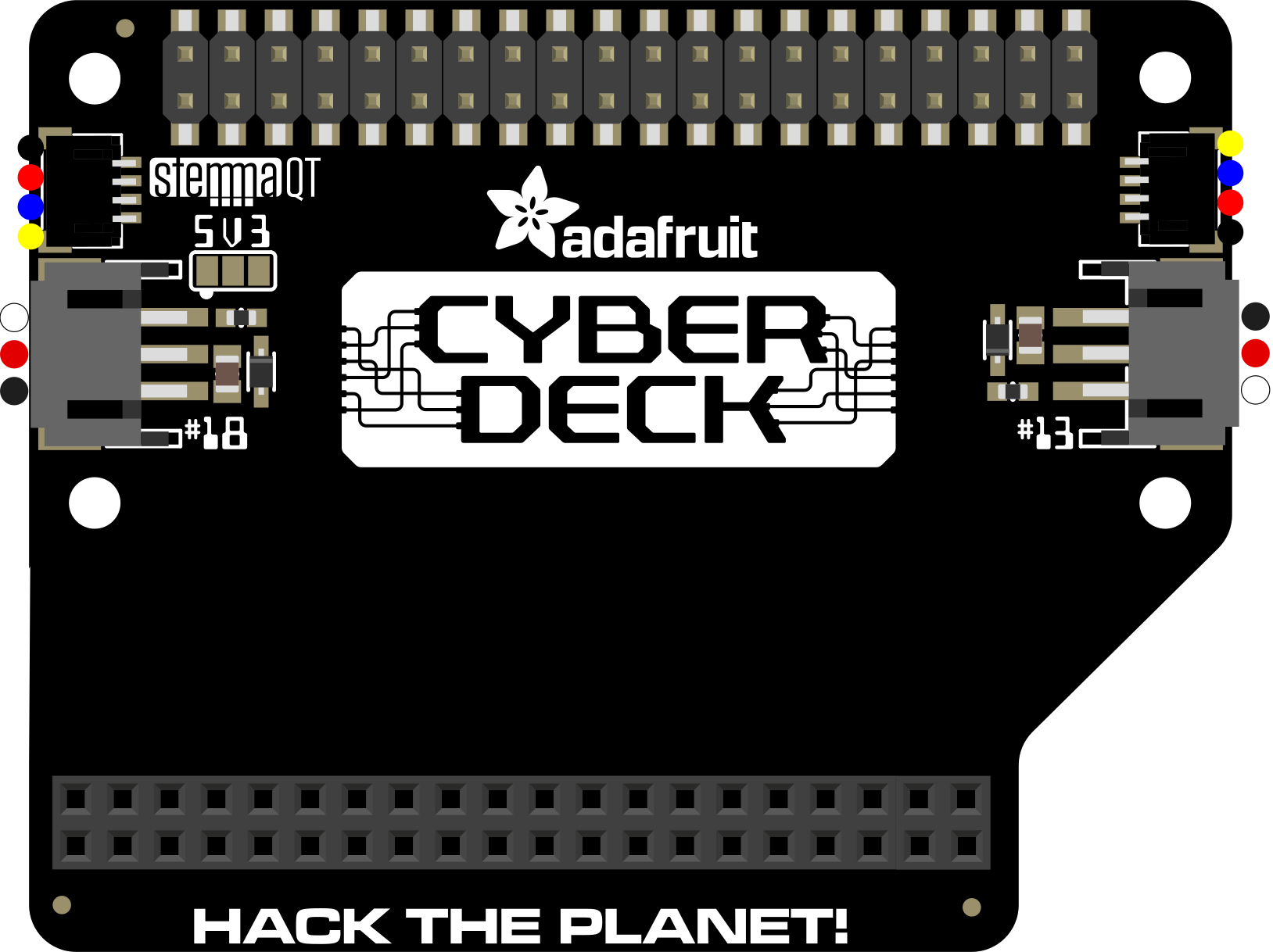
The Adafruit CYBERDECK Bonnet (Part ID: 4862) is a versatile add-on board designed to expand the functionality of Raspberry Pi projects. It features a variety of interfaces and connectors, making it an excellent choice for creating portable computing devices, cyberpunk-inspired builds, or compact embedded systems. This bonnet is compatible with Raspberry Pi boards that have a 40-pin GPIO header and is particularly suited for projects requiring a compact and modular design.
Explore Projects Built with Adafruit CYBERDECK Bonnet
 Open Project in Cirkit Designer
 Open Project in Cirkit Designer
 Open Project in Cirkit Designer
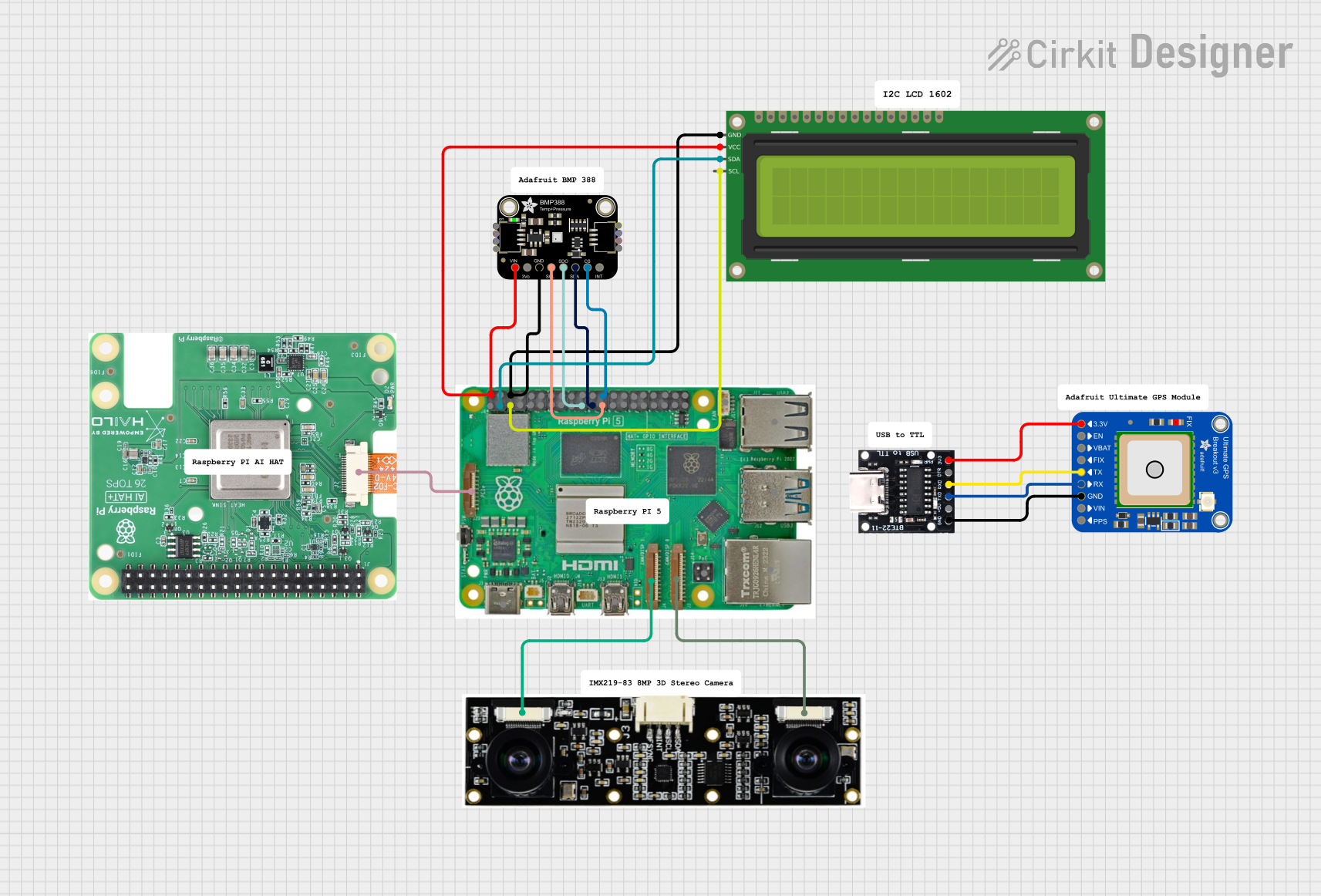 Open Project in Cirkit Designer
Explore Projects Built with Adafruit CYBERDECK Bonnet
Open Project in Cirkit DesignerOpen Project in Cirkit DesignerOpen Project in Cirkit DesignerOpen Project in Cirkit DesignerCommon Applications and Use Cases
- Portable computing devices
- Cyberdeck-style Raspberry Pi builds
- Embedded systems and IoT projects
- Prototyping with Raspberry Pi
- Projects requiring additional GPIO access and modularity
Technical Specifications
The Adafruit CYBERDECK Bonnet is designed to interface seamlessly with Raspberry Pi boards, providing additional connectivity and functionality. Below are the key technical details:
General Specifications
| Parameter | Value |
|---|---|
| Manufacturer | Adafruit |
| Part ID | 4862 |
| Compatibility | Raspberry Pi boards with 40-pin GPIO |
| Dimensions | 65mm x 30mm x 10mm |
| Weight | ~10g |
| Operating Voltage | 3.3V (via Raspberry Pi GPIO header) |
| Operating Temperature | -40°C to 85°C |
Pin Configuration and Descriptions
The CYBERDECK Bonnet connects directly to the Raspberry Pi's 40-pin GPIO header. Below is the pinout description:
| Pin Number | Pin Name | Description |
|---|---|---|
| 1 | 3.3V | Power supply from Raspberry Pi |
| 2 | 5V | Power supply from Raspberry Pi |
| 3 | GPIO2 (SDA1) | I2C Data Line |
| 5 | GPIO3 (SCL1) | I2C Clock Line |
| 7 | GPIO4 | General-purpose I/O |
| 8 | GPIO14 (TXD) | UART Transmit |
| 10 | GPIO15 (RXD) | UART Receive |
| 11 | GPIO17 | General-purpose I/O |
| 13 | GPIO27 | General-purpose I/O |
| 15 | GPIO22 | General-purpose I/O |
| 19 | GPIO10 (MOSI) | SPI Master Out Slave In |
| 21 | GPIO9 (MISO) | SPI Master In Slave Out |
| 23 | GPIO11 (SCLK) | SPI Clock |
| 24 | GPIO8 (CE0) | SPI Chip Enable 0 |
| 26 | GPIO7 (CE1) | SPI Chip Enable 1 |
Note: The remaining pins on the 40-pin GPIO header are pass-through and can be used for other purposes as needed.
Usage Instructions
The Adafruit CYBERDECK Bonnet is easy to use and integrates directly with Raspberry Pi boards. Follow the steps below to get started:
Step 1: Hardware Setup
- Align the CYBERDECK Bonnet with the 40-pin GPIO header on your Raspberry Pi.
- Gently press the bonnet onto the GPIO header until it is securely connected.
- Ensure that the Raspberry Pi is powered off during installation to avoid damage.
Step 2: Software Configuration
- If your project uses I2C, SPI, or UART, enable these interfaces in the Raspberry Pi configuration:
- Open a terminal on your Raspberry Pi.
- Run
sudo raspi-config. - Navigate to Interface Options and enable the required interfaces (I2C, SPI, UART).
- Install any necessary libraries or drivers for your specific project. For example, use the Adafruit Blinka library for Python-based development:
pip3 install adafruit-blinka
Step 3: Example Code
Below is an example Python script to test the I2C interface using the Adafruit Blinka library:
import board
import busio
Initialize I2C interface
i2c = busio.I2C(board.SCL, board.SDA)
Check if I2C devices are connected
if i2c.try_lock(): devices = i2c.scan() # Scan for I2C devices i2c.unlock()
if devices:
    print("I2C devices found:", [hex(device) for device in devices])
else:
    print("No I2C devices found.")
else: print("Unable to access I2C bus.")
Best Practices
- Always power off your Raspberry Pi before attaching or detaching the CYBERDECK Bonnet.
- Use standoffs or spacers to secure the bonnet and prevent accidental disconnection.
- Avoid exceeding the voltage and current ratings of the GPIO pins.
Troubleshooting and FAQs
Common Issues
The CYBERDECK Bonnet is not detected by the Raspberry Pi.
- Ensure the bonnet is properly seated on the GPIO header.
- Verify that the required interfaces (I2C, SPI, UART) are enabled in the Raspberry Pi configuration.
- Check for any physical damage to the GPIO pins or the bonnet.
I2C devices are not detected.
- Confirm that the I2C interface is enabled in
raspi-config. - Check the wiring and ensure that the connected I2C devices are powered and functional.
- Use a multimeter to verify continuity on the SDA and SCL lines.
- Confirm that the I2C interface is enabled in
The Raspberry Pi does not boot after attaching the bonnet.
- Disconnect the bonnet and inspect for any shorts or incorrect connections.
- Ensure that the Raspberry Pi's power supply meets the required specifications.
FAQs
Q: Can I use the CYBERDECK Bonnet with other Raspberry Pi HATs?
A: Yes, the CYBERDECK Bonnet has a pass-through GPIO header, allowing you to stack it with other HATs or bonnets. However, ensure there are no pin conflicts.
Q: Does the CYBERDECK Bonnet support 5V logic?
A: No, the CYBERDECK Bonnet operates at 3.3V logic levels. Ensure that any connected devices are compatible with 3.3V logic.
Q: Can I use the bonnet with Raspberry Pi Zero models?
A: Yes, the CYBERDECK Bonnet is compatible with Raspberry Pi Zero models that have a 40-pin GPIO header.
By following this documentation, you can effectively integrate the Adafruit CYBERDECK Bonnet into your Raspberry Pi projects and troubleshoot any issues that arise.