
How to Use LM2937: Examples, Pinouts, and Specs
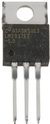
 Design with LM2937 in Cirkit Designer
Introduction
The LM2937ET-3.3/NOPB, manufactured by Texas Instruments, is a low-dropout voltage regulator designed to provide a stable 3.3V output voltage with minimal input-output voltage difference. This component is ideal for applications requiring a regulated power supply, such as battery-powered devices, automotive systems, and industrial equipment. The LM2937 features built-in thermal shutdown and current limiting, ensuring reliable operation and protection against overcurrent and overheating conditions.
Explore Projects Built with LM2937
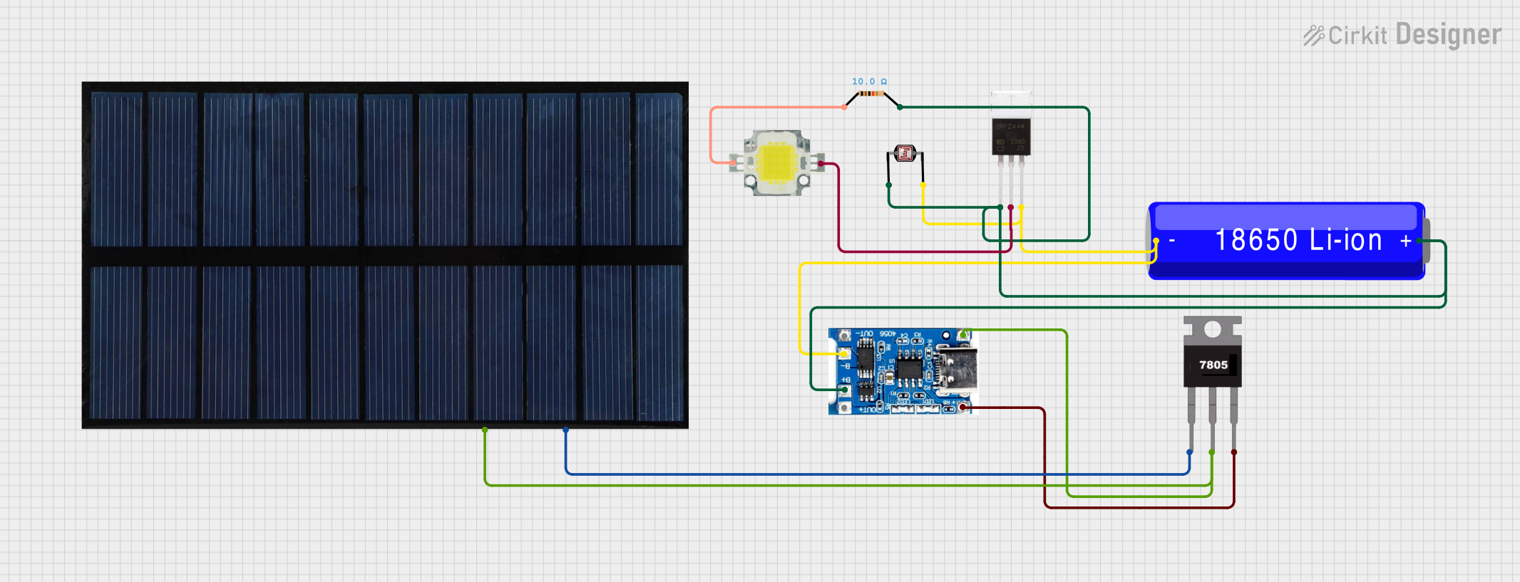 Open Project in Cirkit Designer
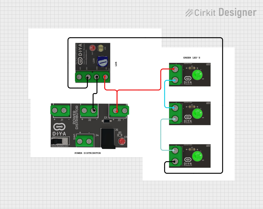 Open Project in Cirkit Designer
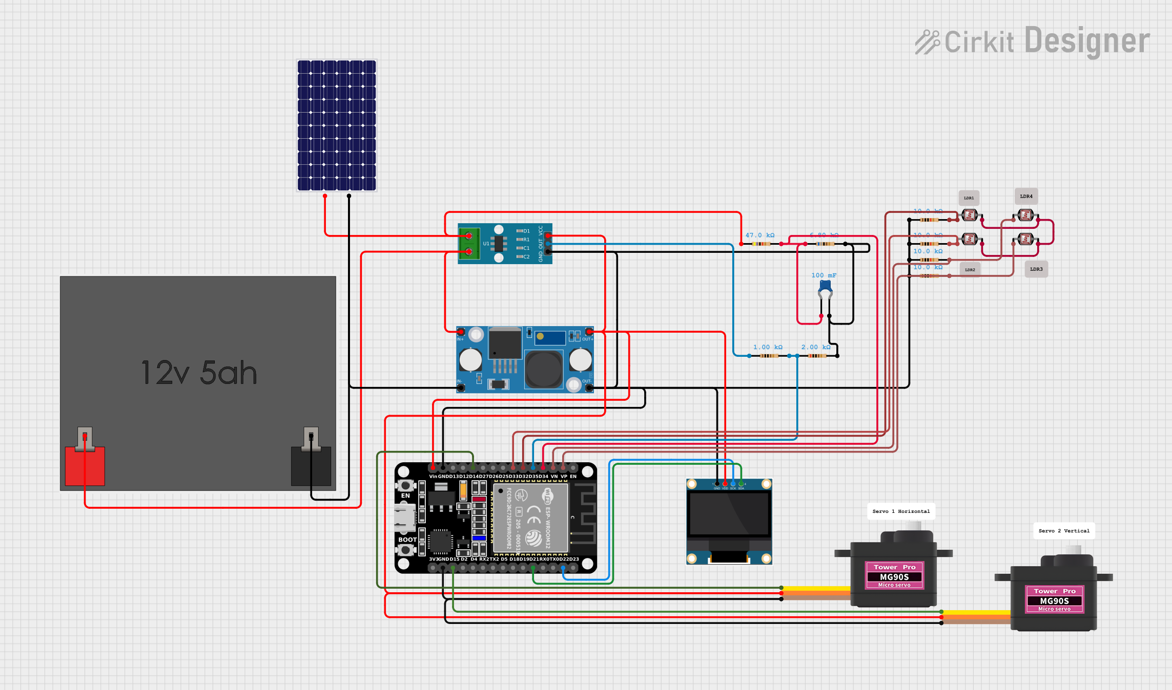 Open Project in Cirkit Designer
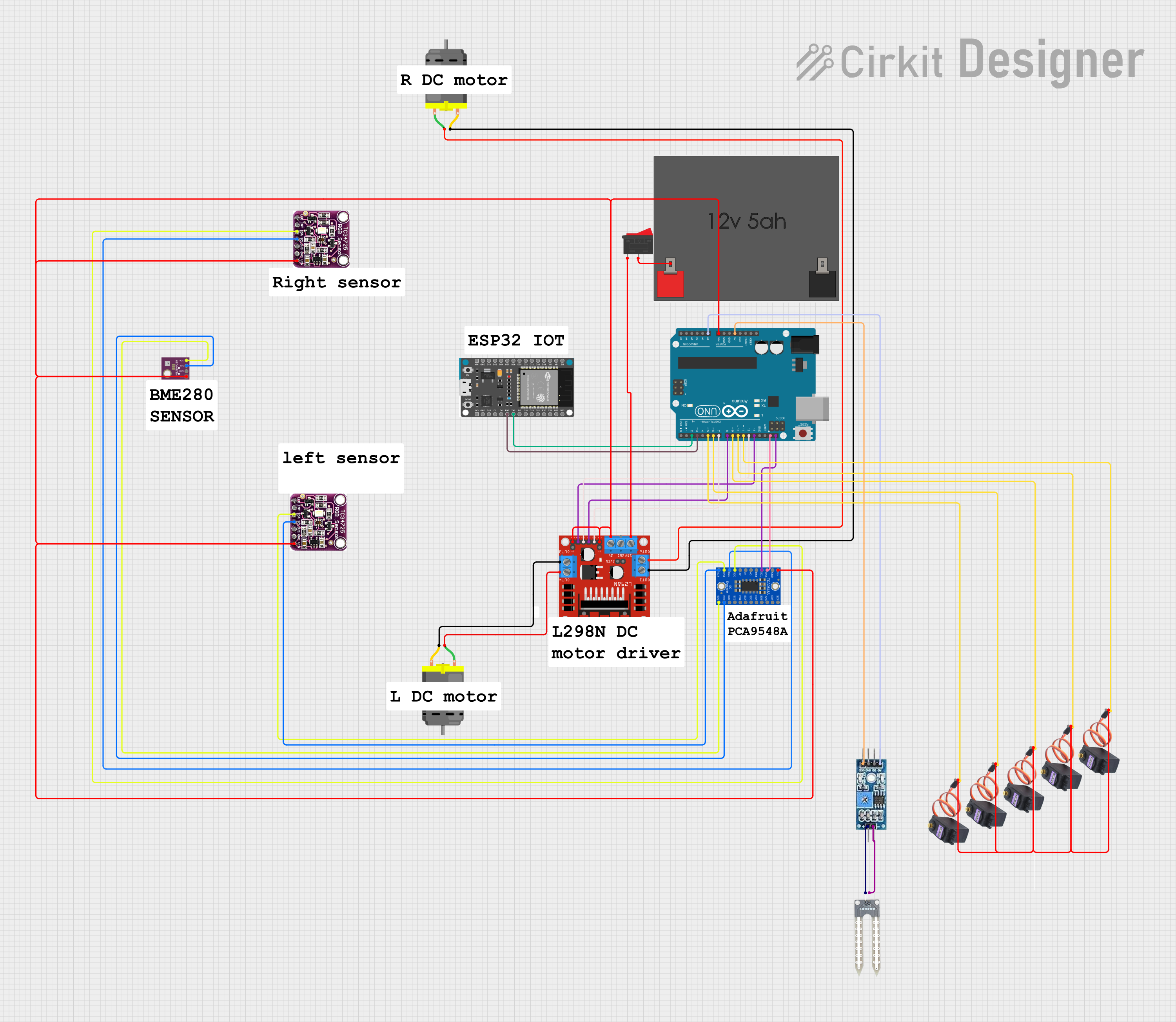 Open Project in Cirkit Designer
Explore Projects Built with LM2937
Open Project in Cirkit DesignerOpen Project in Cirkit DesignerOpen Project in Cirkit DesignerOpen Project in Cirkit DesignerCommon Applications
- Battery-powered devices
- Automotive electronics
- Industrial control systems
- Embedded systems
- Microcontroller-based circuits
Technical Specifications
Key Specifications
| Parameter | Value |
|---|---|
| Output Voltage | 3.3V |
| Input Voltage Range | 4.75V to 26V |
| Maximum Output Current | 500mA |
| Dropout Voltage | 0.5V (typical at 500mA load) |
| Quiescent Current | 10mA (typical) |
| Operating Temperature Range | -40°C to +125°C |
| Package Type | TO-220-3 |
| Protection Features | Thermal shutdown, current limiting |
Pin Configuration
The LM2937ET-3.3/NOPB comes in a TO-220-3 package with the following pinout:
| Pin Number | Pin Name | Description |
|---|---|---|
| 1 | Input | Input voltage (4.75V to 26V) |
| 2 | Ground | Ground connection |
| 3 | Output | Regulated 3.3V output voltage |
Usage Instructions
How to Use the LM2937 in a Circuit
- Input Voltage Requirements: Ensure the input voltage is within the range of 4.75V to 26V. The input voltage must be at least 0.5V higher than the desired output voltage (3.3V) to maintain proper regulation.
- Capacitor Selection:
- Place a 10µF electrolytic capacitor on the input pin to stabilize the input voltage.
- Place a 10µF electrolytic capacitor on the output pin to ensure stable operation and reduce output noise.
- Ensure the capacitors are rated for voltages higher than the input and output voltages.
- Thermal Considerations: The LM2937 generates heat during operation. Use a heatsink with the TO-220 package if the regulator is expected to dissipate significant power.
- Wiring: Connect the input voltage to Pin 1, ground to Pin 2, and the load to Pin 3 (output).
Example Circuit
Below is a basic circuit diagram for using the LM2937 to regulate a 12V input to a 3.3V output:
   +12V Input
       |
       |----[10µF Electrolytic Capacitor]----|
       |                                     |
      Pin 1 (Input)                     Pin 2 (Ground)
       |                                     |
      LM2937                                Load
       |                                     |
      Pin 3 (Output)----[10µF Electrolytic Capacitor]----|
       |                                     |
      +3.3V Output                          Ground
Using LM2937 with Arduino UNO
The LM2937 can be used to power an Arduino UNO by providing a stable 3.3V supply. Below is an example of Arduino code to read an analog sensor powered by the LM2937:
// Example: Reading an analog sensor powered by LM2937
// Ensure the LM2937 provides a stable 3.3V to the sensor and Arduino's 3.3V pin.

const int sensorPin = A0; // Analog pin connected to the sensor output
int sensorValue = 0;      // Variable to store the sensor reading

void setup() {
  Serial.begin(9600); // Initialize serial communication at 9600 baud
}

void loop() {
  sensorValue = analogRead(sensorPin); // Read the sensor value
  float voltage = sensorValue * (3.3 / 1023.0); // Convert to voltage (3.3V reference)

  // Print the sensor value and voltage to the Serial Monitor
  Serial.print("Sensor Value: ");
  Serial.print(sensorValue);
  Serial.print(" | Voltage: ");
  Serial.print(voltage);
  Serial.println(" V");

  delay(1000); // Wait for 1 second before the next reading
}
Best Practices
- Always use the recommended input and output capacitors to ensure stability.
- Avoid exceeding the maximum input voltage (26V) or output current (500mA).
- Use a heatsink if the regulator operates under high current or high input voltage conditions.
- Place the capacitors as close as possible to the regulator pins to minimize noise and improve stability.
Troubleshooting and FAQs
Common Issues and Solutions
| Issue | Possible Cause | Solution |
|---|---|---|
| Output voltage is unstable | Missing or incorrect output capacitor | Use a 10µF electrolytic capacitor on the output pin. |
| Regulator overheats | Excessive power dissipation | Use a heatsink or reduce the input voltage. |
| No output voltage | Incorrect wiring or damaged component | Verify connections and ensure the input voltage is within range. |
| High output noise | Insufficient input/output filtering | Add or replace capacitors with higher-quality ones. |
FAQs
Can the LM2937 provide more than 500mA output current?
- No, the LM2937 is rated for a maximum output current of 500mA. Exceeding this limit may trigger current limiting or damage the component.
What happens if the input voltage drops below 4.75V?
- The regulator may fail to maintain a stable 3.3V output, leading to voltage drops or instability.
Can I use ceramic capacitors instead of electrolytic capacitors?
- While ceramic capacitors can be used, it is recommended to use electrolytic capacitors for better stability and performance, especially for the output capacitor.
Is the LM2937 suitable for powering microcontrollers?
- Yes, the LM2937 is ideal for powering microcontrollers and other low-power devices requiring a stable 3.3V supply.
By following the guidelines and recommendations in this documentation, you can effectively use the LM2937ET-3.3/NOPB in your projects for reliable and stable voltage regulation.