Cirkit Designer Logo
Cirkit Designer
Your all-in-one circuit design IDE
Home / 
Component Documentation

How to Use LED matrix 8x32 DOT: Examples, Pinouts, and Specs

Image of LED matrix 8x32 DOT
Cirkit Designer LogoDesign with LED matrix 8x32 DOT in Cirkit Designer

Introduction

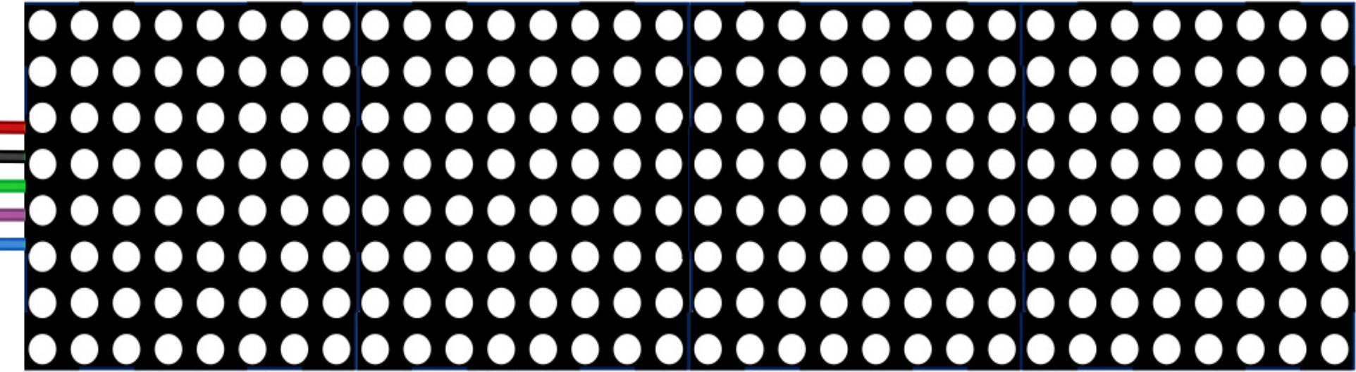
The AZDelivery MAX7219 8x32 LED Matrix is a versatile display module consisting of 8 rows and 32 columns of individually addressable LEDs. This component is powered by the MAX7219 driver IC, which simplifies the control of the LED matrix by reducing the number of required microcontroller pins. It is ideal for creating scrolling text, animations, and visual indicators in a compact and efficient form factor.

Explore Projects Built with LED matrix 8x32 DOT

Use Cirkit Designer to design, explore, and prototype these projects online. Some projects support real-time simulation. Click "Open Project" to start designing instantly!
ESP32-Controlled WS2812 LED Matrix Display with Resistor
Image of esp32 door sign project: A project utilizing LED matrix 8x32 DOT in a practical application
This circuit features an ESP32 microcontroller connected to a 32x8 WS2812 LED matrix. The ESP32 controls the LED matrix through a 220-ohm resistor connected to its D12 pin, providing data input to the matrix, while power and ground connections are shared between the ESP32 and the LED matrix.
Cirkit Designer LogoOpen Project in Cirkit Designer
ESP32-Controlled Dual 8x8 LED Matrix Display with NTP Time Synchronization
Image of time: A project utilizing LED matrix 8x32 DOT in a practical application
This circuit features an ESP32 microcontroller connected to two cascaded 8x8 LED matrix displays, powered by a 3.3V battery. The ESP32 drives the displays to show time and other information, with the code indicating functionality for connecting to WiFi, synchronizing time via NTP, and displaying data on the matrices using custom fonts. Additionally, there is a separate 3.3V battery powering a red LED, which appears to function as a simple indicator light.
Cirkit Designer LogoOpen Project in Cirkit Designer
ESP8266 NodeMCU Controlled 8x8 LED Matrix Display
Image of Nodemcu: A project utilizing LED matrix 8x32 DOT in a practical application
This circuit connects an ESP8266 NodeMCU microcontroller to an 8x8 LED matrix display. The NodeMCU controls the matrix using digital pins D5, D7, and D8 for chip select (CS), data input (DIN), and clock (CLK) signals, respectively. The circuit is designed to display patterns or characters on the LED matrix, which are driven by the microcontroller.
Cirkit Designer LogoOpen Project in Cirkit Designer
ESP32-Based Smart Weather Station with LED Display and Multiple Sensors
Image of Copy of Zegarek (1): A project utilizing LED matrix 8x32 DOT in a practical application
This circuit is a sensor and display system powered by an ESP32 microcontroller. It integrates multiple sensors (BH1750 light sensor, BMP280 pressure sensor, DS3231 RTC, and DS18B20 temperature sensor) and drives a series of MAX7219 8x8 LED matrices for visual output. The ESP32 communicates with the sensors via I2C and controls the LED matrices to display data.
Cirkit Designer LogoOpen Project in Cirkit Designer

Explore Projects Built with LED matrix 8x32 DOT

Use Cirkit Designer to design, explore, and prototype these projects online. Some projects support real-time simulation. Click "Open Project" to start designing instantly!
Image of esp32 door sign project: A project utilizing LED matrix 8x32 DOT in a practical application
ESP32-Controlled WS2812 LED Matrix Display with Resistor
This circuit features an ESP32 microcontroller connected to a 32x8 WS2812 LED matrix. The ESP32 controls the LED matrix through a 220-ohm resistor connected to its D12 pin, providing data input to the matrix, while power and ground connections are shared between the ESP32 and the LED matrix.
Cirkit Designer LogoOpen Project in Cirkit Designer
Image of time: A project utilizing LED matrix 8x32 DOT in a practical application
ESP32-Controlled Dual 8x8 LED Matrix Display with NTP Time Synchronization
This circuit features an ESP32 microcontroller connected to two cascaded 8x8 LED matrix displays, powered by a 3.3V battery. The ESP32 drives the displays to show time and other information, with the code indicating functionality for connecting to WiFi, synchronizing time via NTP, and displaying data on the matrices using custom fonts. Additionally, there is a separate 3.3V battery powering a red LED, which appears to function as a simple indicator light.
Cirkit Designer LogoOpen Project in Cirkit Designer
Image of Nodemcu: A project utilizing LED matrix 8x32 DOT in a practical application
ESP8266 NodeMCU Controlled 8x8 LED Matrix Display
This circuit connects an ESP8266 NodeMCU microcontroller to an 8x8 LED matrix display. The NodeMCU controls the matrix using digital pins D5, D7, and D8 for chip select (CS), data input (DIN), and clock (CLK) signals, respectively. The circuit is designed to display patterns or characters on the LED matrix, which are driven by the microcontroller.
Cirkit Designer LogoOpen Project in Cirkit Designer
Image of Copy of Zegarek (1): A project utilizing LED matrix 8x32 DOT in a practical application
ESP32-Based Smart Weather Station with LED Display and Multiple Sensors
This circuit is a sensor and display system powered by an ESP32 microcontroller. It integrates multiple sensors (BH1750 light sensor, BMP280 pressure sensor, DS3231 RTC, and DS18B20 temperature sensor) and drives a series of MAX7219 8x8 LED matrices for visual output. The ESP32 communicates with the sensors via I2C and controls the LED matrices to display data.
Cirkit Designer LogoOpen Project in Cirkit Designer

Common Applications

  • Scrolling text displays
  • Digital clocks and counters
  • Visual indicators for IoT devices
  • Simple animations and graphics
  • Educational projects and prototyping

Technical Specifications

Below are the key technical details for the AZDelivery MAX7219 8x32 LED Matrix:

Parameter Value
Manufacturer AZDelivery
Part ID MAX7219 8x32
Operating Voltage 5V DC
Current Consumption ~320mA (typical, depends on usage)
Communication Protocol SPI (Serial Peripheral Interface)
Dimensions 32mm x 128mm x 15mm
LED Configuration 8 rows x 32 columns
Driver IC MAX7219

Pin Configuration

The LED matrix has a 5-pin interface for connecting to a microcontroller. The pinout is as follows:

Pin Name Description
1 VCC Power supply input (5V DC)
2 GND Ground connection
3 DIN Data input for serial communication
4 CS Chip select (active low)
5 CLK Clock input for synchronizing data transmission

Usage Instructions

Connecting the LED Matrix to an Arduino UNO

To use the AZDelivery MAX7219 8x32 LED Matrix with an Arduino UNO, follow these steps:

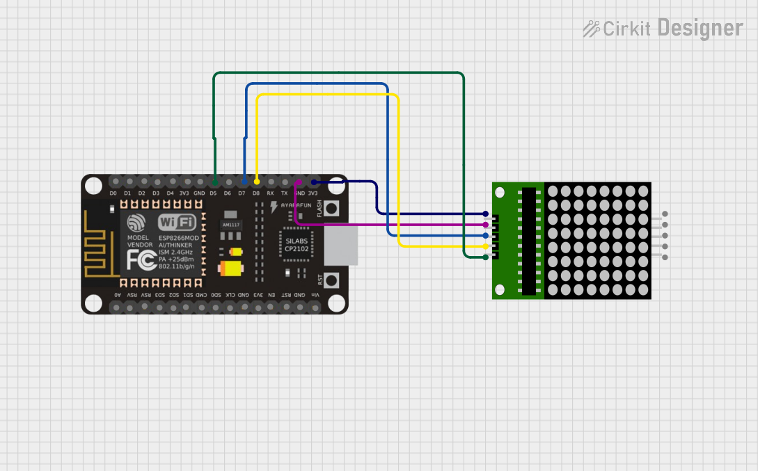
  1. Wiring: Connect the LED matrix to the Arduino UNO as shown below:

    • VCC5V on Arduino
    • GNDGND on Arduino
    • DIND11 (MOSI pin on Arduino UNO)
    • CSD10
    • CLKD13 (SCK pin on Arduino UNO)
  2. Install Required Library: Install the LedControl library in the Arduino IDE:

    • Go to Sketch > Include Library > Manage Libraries.
    • Search for "LedControl" and install it.
  3. Upload Example Code: Use the following example code to display scrolling text on the LED matrix:

#include <LedControl.h>

// Initialize the LED matrix (DIN=D11, CLK=D13, CS=D10, 1 device)
LedControl lc = LedControl(11, 13, 10, 1);

void setup() {
  // Wake up the MAX7219 from power-saving mode
  lc.shutdown(0, false);
  // Set brightness level (0 = dim, 15 = bright)
  lc.setIntensity(0, 8);
  // Clear the display
  lc.clearDisplay(0);

  // Display a simple pattern (e.g., a horizontal line)
  for (int row = 0; row < 8; row++) {
    lc.setRow(0, row, 0xFF); // Turn on all LEDs in each row
  }
}

void loop() {
  // Add your scrolling text or animation logic here
}

Important Considerations

  • Power Supply: Ensure the module is powered with a stable 5V DC source. Using a higher voltage may damage the LEDs or the MAX7219 IC.
  • Current Limitation: Avoid driving all LEDs at full brightness simultaneously, as this can exceed the current rating of the module.
  • Daisy-Chaining: Multiple MAX7219 modules can be daisy-chained to create larger displays. Connect the DOUT pin of one module to the DIN pin of the next.

Troubleshooting and FAQs

Common Issues and Solutions

  1. No Display Output

    • Cause: Incorrect wiring or loose connections.
    • Solution: Double-check all connections, especially DIN, CS, and CLK.
  2. Flickering LEDs

    • Cause: Insufficient power supply or unstable voltage.
    • Solution: Use a dedicated 5V power source with sufficient current capacity.
  3. Partial Display Not Working

    • Cause: Faulty LED matrix or driver IC.
    • Solution: Test the module with a different microcontroller or replace the faulty module.
  4. Scrolling Text Not Displaying Properly

    • Cause: Incorrect library configuration or code logic.
    • Solution: Verify the library installation and ensure the code matches the module's configuration.

FAQs

Q1: Can I use this module with a 3.3V microcontroller?
A1: The MAX7219 requires a 5V power supply, but its logic pins are 3.3V-tolerant. Use a level shifter if needed for reliable operation.

Q2: How many modules can I daisy-chain together?
A2: Up to 8 modules can be daisy-chained, but this depends on the microcontroller's memory and processing power.

Q3: Can I control individual LEDs?
A3: Yes, the MAX7219 allows precise control of each LED by addressing its row and column.

Q4: Is the brightness adjustable?
A4: Yes, the brightness can be adjusted programmatically using the setIntensity() function in the LedControl library.

By following this documentation, you can effectively integrate the AZDelivery MAX7219 8x32 LED Matrix into your projects and create stunning visual displays.