
How to Use UM-FPU_V3_1: Examples, Pinouts, and Specs
 Design with UM-FPU_V3_1 in Cirkit Designer
Introduction
The UM-FPU V3.1, manufactured by Micromega Corporation, is a high-performance floating-point unit (FPU) designed to handle complex arithmetic operations efficiently. It is particularly suited for real-time processing in embedded systems, where computational speed and precision are critical. This component offloads floating-point calculations from the main microcontroller, significantly improving overall system performance.
Explore Projects Built with UM-FPU_V3_1
 Open Project in Cirkit Designer
 Open Project in Cirkit Designer
 Open Project in Cirkit Designer
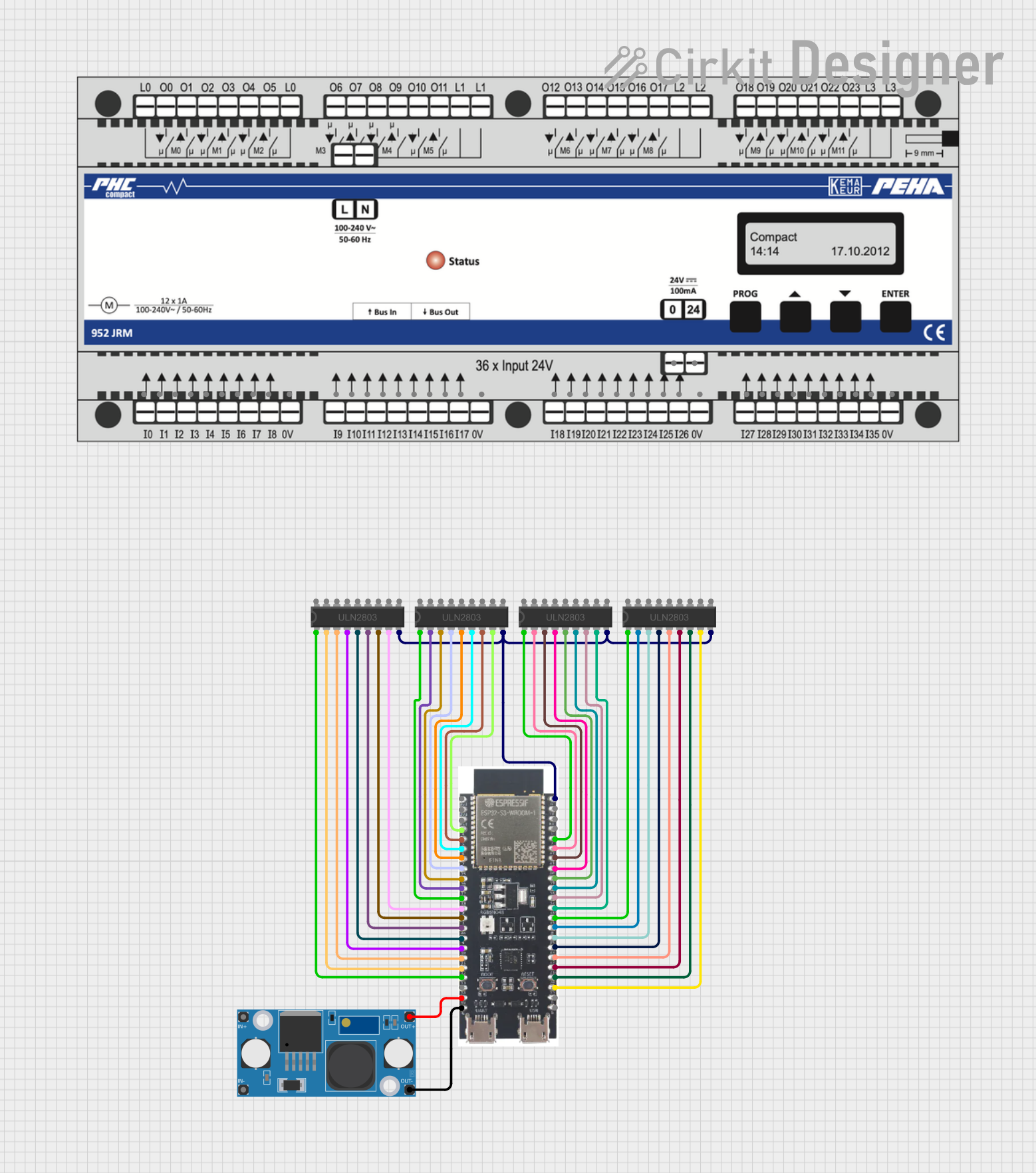 Open Project in Cirkit Designer
Explore Projects Built with UM-FPU_V3_1
Open Project in Cirkit DesignerOpen Project in Cirkit DesignerOpen Project in Cirkit DesignerOpen Project in Cirkit DesignerCommon Applications and Use Cases
- Robotics and automation systems requiring real-time calculations
- Signal processing and data analysis
- Scientific instrumentation
- Embedded systems with limited computational resources
- Applications requiring trigonometric, logarithmic, or exponential calculations
Technical Specifications
Key Technical Details
- Manufacturer Part ID: uM-FPU V3.1
- Operating Voltage: 3.3V to 5.0V
- Operating Current: 3.5 mA (typical)
- Communication Interface: I²C, SPI, or UART
- Clock Speed: 32 MHz
- Package Type: 28-pin DIP or SOIC
- Temperature Range: -40°C to +85°C
- Arithmetic Support: Single-precision floating-point (IEEE 754 compliant)
- Additional Features:
- Built-in trigonometric, logarithmic, and exponential functions
- 32-bit integer and floating-point operations
- User-programmable registers and memory
Pin Configuration and Descriptions
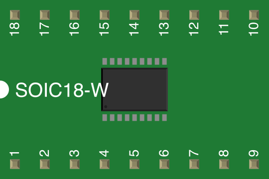
The UM-FPU V3.1 is available in a 28-pin DIP or SOIC package. Below is the pin configuration:
| Pin Number | Pin Name | Description |
|---|---|---|
| 1 | VDD | Positive power supply (3.3V to 5.0V). |
| 2 | GND | Ground connection. |
| 3 | RESET | Active-low reset input. |
| 4 | SCL | I²C clock line (shared with SPI clock). |
| 5 | SDA | I²C data line (shared with SPI MOSI). |
| 6 | SS | SPI slave select (active low). |
| 7 | TX | UART transmit line. |
| 8 | RX | UART receive line. |
| 9-20 | GPIO[0-11] | General-purpose input/output pins (user-configurable). |
| 21 | OSC1 | External clock input (optional). |
| 22 | OSC2 | External clock output (optional). |
| 23-28 | NC | No connection (reserved for future use). |
Usage Instructions
How to Use the UM-FPU V3.1 in a Circuit
- Power Supply: Connect the VDD pin to a 3.3V or 5.0V power source and the GND pin to ground.
- Communication Interface: Choose one of the supported communication protocols (I²C, SPI, or UART) and connect the corresponding pins:
- For I²C: Connect SCL and SDA to the microcontroller's I²C lines.
- For SPI: Connect SCL (SPI clock), SDA (MOSI), and SS (slave select) to the microcontroller's SPI lines.
- For UART: Connect TX and RX to the microcontroller's UART lines.
- Reset: Optionally connect the RESET pin to a microcontroller GPIO pin for manual or software-controlled resets.
- GPIO Pins: Use the GPIO pins for additional input/output functionality as needed.
- Clock: If required, connect an external clock source to OSC1 and OSC2.
Important Considerations and Best Practices
- Ensure the power supply voltage matches the operating voltage range (3.3V to 5.0V).
- Use pull-up resistors (typically 4.7kΩ) on the I²C lines (SCL and SDA) if using the I²C interface.
- Avoid leaving unused communication pins floating; tie them to ground or VDD as appropriate.
- Use decoupling capacitors (e.g., 0.1 µF) near the VDD pin to reduce noise and improve stability.
- Refer to the manufacturer's datasheet for detailed timing diagrams and electrical characteristics.
Example: Connecting UM-FPU V3.1 to an Arduino UNO (I²C)
Below is an example of how to connect and program the UM-FPU V3.1 with an Arduino UNO using the I²C interface.
Circuit Diagram
- Connect the UM-FPU V3.1's SCL and SDA pins to the Arduino's A5 (SCL) and A4 (SDA) pins, respectively.
- Connect VDD to the Arduino's 5V pin and GND to the Arduino's GND pin.
- Add 4.7kΩ pull-up resistors to the SCL and SDA lines.
Arduino Code
#include <Wire.h> // Include the Wire library for I²C communication

#define FPU_ADDRESS 0x60 // Default I²C address of the UM-FPU V3.1

void setup() {
  Wire.begin(); // Initialize I²C communication
  Serial.begin(9600); // Initialize serial communication for debugging

  // Send a reset command to the UM-FPU V3.1
  Wire.beginTransmission(FPU_ADDRESS);
  Wire.write(0x01); // Example command: Reset the FPU
  Wire.endTransmission();

  Serial.println("UM-FPU V3.1 initialized.");
}

void loop() {
  // Example: Send a floating-point number to the FPU
  Wire.beginTransmission(FPU_ADDRESS);
  Wire.write(0x10); // Example command: Load a floating-point value
  Wire.write(0x42); // High byte of the floating-point value
  Wire.write(0x48); // Low byte of the floating-point value
  Wire.endTransmission();

  delay(1000); // Wait for 1 second
}
Troubleshooting and FAQs
Common Issues and Solutions
The UM-FPU V3.1 is not responding to commands.
- Verify the power supply voltage is within the specified range (3.3V to 5.0V).
- Check the communication interface connections (I²C, SPI, or UART) for loose or incorrect wiring.
- Ensure pull-up resistors are present on the I²C lines if using the I²C interface.
Incorrect or unexpected calculation results.
- Confirm that the input data format matches the expected format (e.g., IEEE 754 for floating-point values).
- Check for communication errors or data corruption during transmission.
The device overheats during operation.
- Ensure the power supply is stable and within the specified voltage range.
- Verify that the GPIO pins are not sourcing or sinking excessive current.
FAQs
Q: Can the UM-FPU V3.1 handle double-precision floating-point operations?
A: No, the UM-FPU V3.1 supports single-precision floating-point operations only (IEEE 754 compliant).
Q: What is the maximum clock speed of the UM-FPU V3.1?
A: The UM-FPU V3.1 operates at a maximum clock speed of 32 MHz.
Q: Can I use the UM-FPU V3.1 with a 3.3V microcontroller?
A: Yes, the UM-FPU V3.1 is compatible with both 3.3V and 5.0V systems.
Q: Is there a library available for Arduino?
A: Yes, Micromega Corporation provides an Arduino library for the UM-FPU V3.1, which simplifies integration and usage. Refer to the manufacturer's website for more details.