How to Use Module: Examples, Pinouts, and Specs
Introduction
A module is a self-contained unit of functionality that integrates various electronic components and circuitry into a single package. Modules are designed to simplify complex designs, enhance reusability, and reduce development time in electronic systems. They are widely used in prototyping, embedded systems, and production-level designs.
Common applications of modules include:
- Wireless communication (e.g., Wi-Fi, Bluetooth modules)
- Sensor integration (e.g., temperature, humidity, or motion sensor modules)
- Power management (e.g., voltage regulator modules)
- Motor control (e.g., motor driver modules)
- Display interfaces (e.g., LCD or OLED display modules)
Explore Projects Built with Module

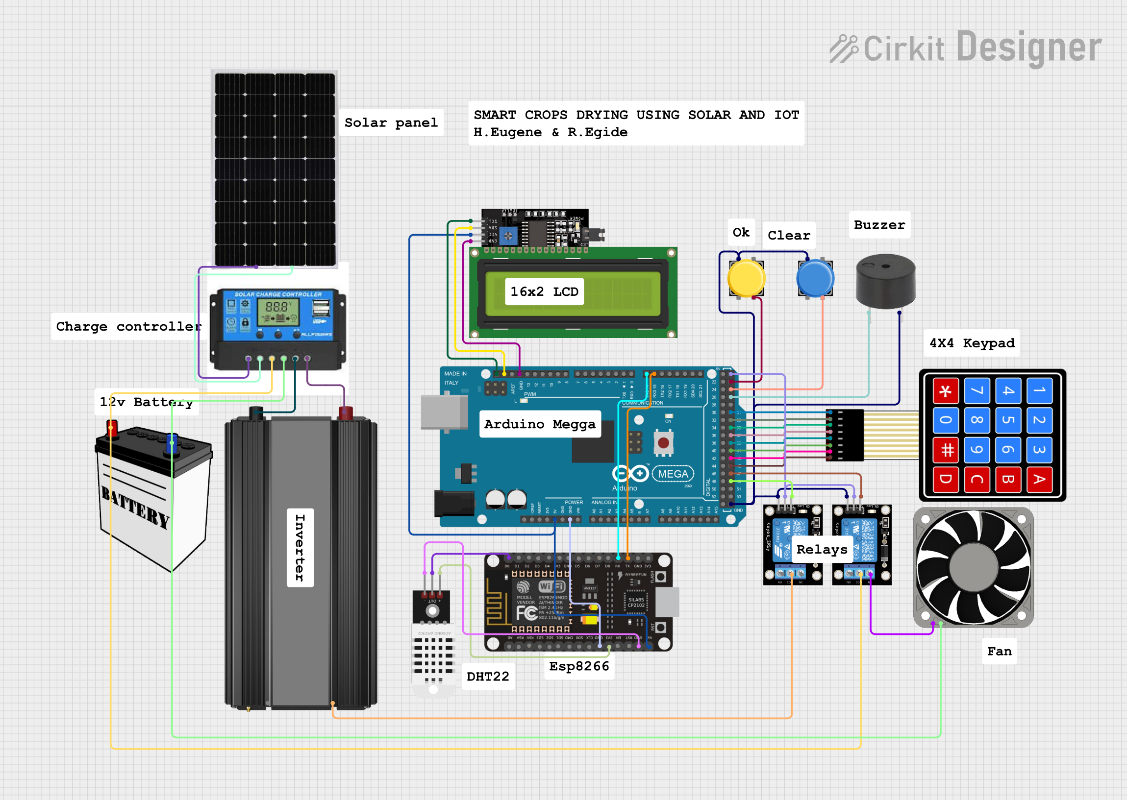
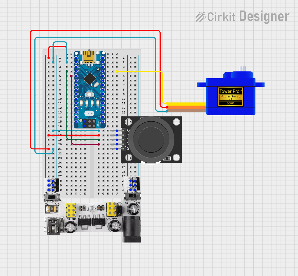
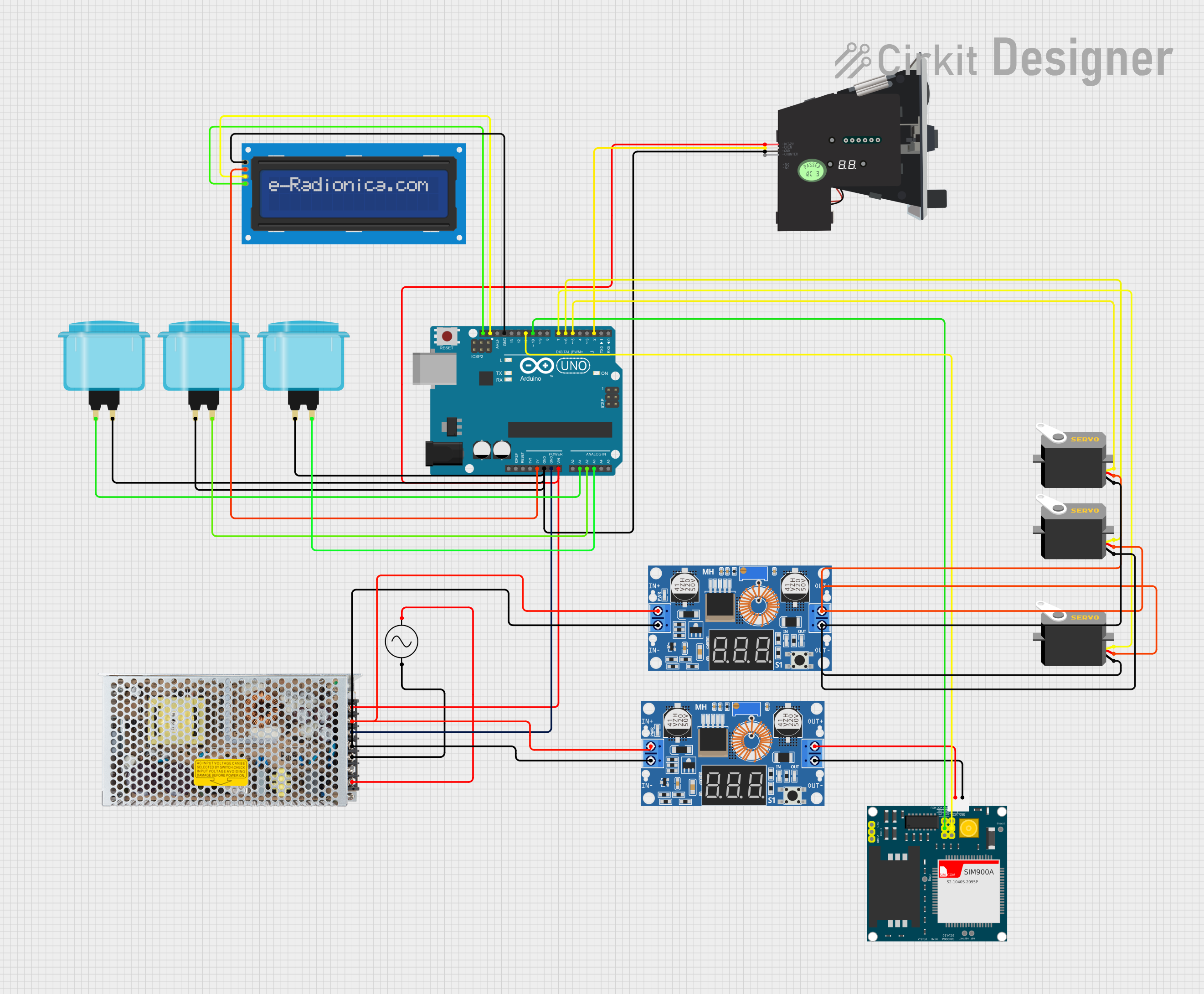
Explore Projects Built with Module
Technical Specifications
Modules come in a variety of types, each with its own specifications. Below is an example of a generic module's technical specifications:
Example Specifications for a Generic Module
| Parameter | Value |
|---|---|
| Operating Voltage | 3.3V - 5V |
| Operating Current | 10mA - 500mA (varies by type) |
| Communication Interface | I2C, SPI, UART, or GPIO |
| Dimensions | Varies (e.g., 25mm x 30mm) |
| Operating Temperature | -40°C to +85°C |
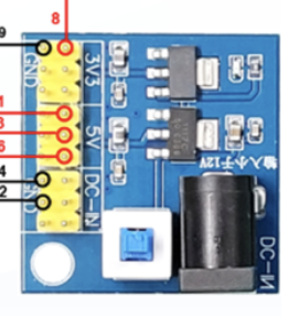
Example Pin Configuration
| Pin Number | Pin Name | Description |
|---|---|---|
| 1 | VCC | Power supply input (3.3V or 5V) |
| 2 | GND | Ground connection |
| 3 | DATA | Data input/output (depends on module type) |
| 4 | CLK | Clock signal (for I2C/SPI modules) |
| 5 | EN | Enable pin (used to activate the module) |
Note: The exact pin configuration and specifications will vary depending on the type of module being used. Always refer to the datasheet or manufacturer documentation for precise details.
Usage Instructions
How to Use the Module in a Circuit
- Power the Module: Connect the VCC pin to a 3.3V or 5V power source (as specified for the module) and the GND pin to the ground of your circuit.
- Connect Communication Pins: Depending on the module type, connect the communication pins (e.g., DATA, CLK) to the corresponding pins on your microcontroller or development board.
- Enable the Module: If the module has an enable (EN) pin, ensure it is set to the appropriate logic level (e.g., HIGH) to activate the module.
- Write Code: Use the appropriate library or communication protocol (e.g., I2C, SPI, UART) to interface with the module.
Important Considerations and Best Practices
- Voltage Compatibility: Ensure the module's operating voltage matches your circuit's power supply. Using an incorrect voltage can damage the module.
- Pin Connections: Double-check all pin connections to avoid short circuits or incorrect wiring.
- Heat Dissipation: If the module generates heat during operation, ensure proper ventilation or heat sinking.
- Datasheet Reference: Always consult the module's datasheet for specific details, such as pinout, timing requirements, and electrical characteristics.
Example: Using a Module with Arduino UNO
Below is an example of interfacing a generic I2C module with an Arduino UNO:
#include <Wire.h> // Include the Wire library for I2C communication

#define MODULE_ADDRESS 0x3C // Replace with the module's I2C address

void setup() {
  Wire.begin(); // Initialize I2C communication
  Serial.begin(9600); // Start serial communication for debugging

  // Send initialization command to the module
  Wire.beginTransmission(MODULE_ADDRESS);
  Wire.write(0x00); // Example command to initialize the module
  Wire.endTransmission();

  Serial.println("Module initialized.");
}

void loop() {
  // Example: Read data from the module
  Wire.requestFrom(MODULE_ADDRESS, 1); // Request 1 byte of data
  if (Wire.available()) {
    int data = Wire.read(); // Read the data
    Serial.print("Data received: ");
    Serial.println(data);
  }

  delay(1000); // Wait for 1 second before the next read
}
Note: Replace MODULE_ADDRESS and the initialization command with values specific to your module.
Troubleshooting and FAQs
Common Issues and Solutions
Module Not Powering On:
- Cause: Incorrect voltage or loose connections.
- Solution: Verify the power supply voltage and ensure all connections are secure.
No Communication with Microcontroller:
- Cause: Incorrect communication protocol or wiring.
- Solution: Check the module's datasheet for the correct protocol and pin connections. Ensure the microcontroller's pins are configured correctly.
Data Corruption or Noise:
- Cause: Long wires or interference.
- Solution: Use shorter wires and, if necessary, add pull-up resistors or shielding to reduce noise.
Overheating:
- Cause: Excessive current draw or poor ventilation.
- Solution: Ensure the module is operating within its specified current range and provide adequate cooling.
FAQs
Q: Can I use a 5V module with a 3.3V microcontroller?
A: It depends on the module. Some modules have built-in level shifters to support 3.3V logic, while others require external level shifting. Check the module's datasheet for compatibility.
Q: How do I find the I2C address of my module?
A: Use an I2C scanner sketch on your microcontroller to detect the module's address. This is especially useful if the address is not listed in the documentation.
Q: Can multiple modules be connected to the same microcontroller?
A: Yes, as long as the microcontroller has enough pins or supports multiple devices on the same communication bus (e.g., I2C or SPI). Ensure each module has a unique address or chip select pin.
By following this documentation, you can effectively integrate and troubleshoot modules in your electronic projects. Always refer to the specific module's datasheet for detailed information.