How to Use 40 Fan 12v: Examples, Pinouts, and Specs
Introduction
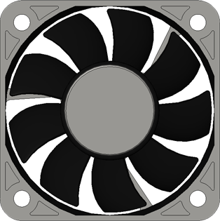
The 40mm 12V Cooling Fan is an essential component widely used in various electronic and computing applications to maintain optimal operating temperatures. Its primary function is to provide airflow over heated components, such as CPUs, power supplies, and other heat-generating electronic devices, to prevent overheating and ensure reliable performance.
Explore Projects Built with 40 Fan 12v


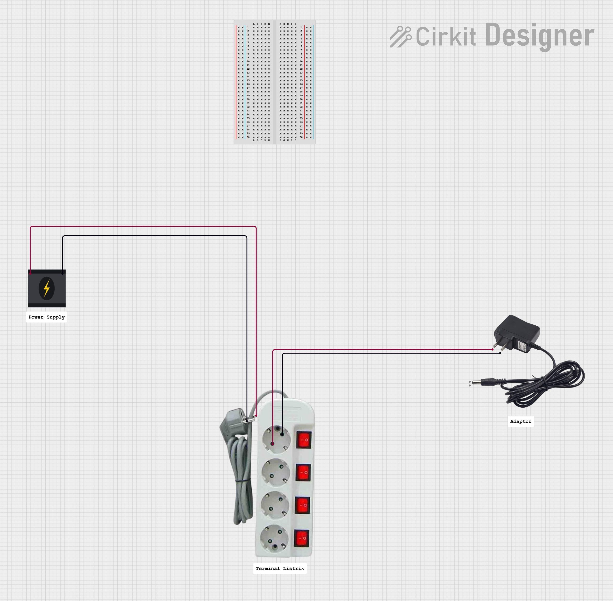
Explore Projects Built with 40 Fan 12v
Common Applications and Use Cases
- Cooling CPUs in computers and servers
- Ventilation for 3D printers and electronic enclosures
- Component cooling in power supplies and amplifiers
- Thermal management in LED lighting systems
Technical Specifications
Key Technical Details
| Parameter | Specification |
|---|---|
| Operating Voltage | 12V DC |
| Current | Typically 0.1 to 0.3A (depending on model) |
| Power Consumption | 1.2W to 3.6W (depending on model) |
| Airflow | Varies by model, check datasheet |
| Noise Level | Varies by model, check datasheet |
| Bearing Type | Sleeve/Ball (model-dependent) |
| Lifespan | 30,000 - 60,000 hours (model-dependent) |
Pin Configuration and Descriptions
| Pin Number | Description |
|---|---|
| 1 | Ground (-) |
| 2 | +12V DC Power (+) |
| 3 | Tachometer Signal (optional) |
| 4 | PWM Control Signal (optional) |
Note: Pins 3 and 4 may not be present on all models. Check the datasheet for your specific fan model.
Usage Instructions
How to Use the Component in a Circuit
- Power Connection: Connect pin 1 to the ground of your power supply and pin 2 to the +12V DC line. Ensure that the power supply can handle the current draw of the fan.
- Tachometer (Optional): If available, connect pin 3 to a tachometer input on your system to monitor fan speed.
- PWM Control (Optional): If available, connect pin 4 to a PWM output to control the fan speed.
Important Considerations and Best Practices
- Voltage Rating: Do not exceed the rated voltage of 12V DC as it may damage the fan.
- Current Draw: Ensure your power supply can provide sufficient current for the fan's operation.
- Airflow Direction: Install the fan so that it directs air over the component(s) that require cooling. The airflow direction is usually indicated by an arrow on the fan housing.
- Mounting: Secure the fan using appropriate screws or mounts to prevent vibrations and noise.
- Dust Filters: Consider using dust filters to prevent dust accumulation on the fan and the components it cools.
- Regular Maintenance: Periodically clean the fan blades and bearings to maintain optimal performance and extend the fan's lifespan.
Troubleshooting and FAQs
Common Issues
- Fan Does Not Start: Check the power connections and ensure the voltage is within the specified range. Inspect for any obstructions that may prevent the fan blades from spinning.
- Noisy Operation: Verify that the fan is securely mounted. Excessive noise can also be a sign of dust buildup or bearing wear.
- Inadequate Cooling: Ensure the fan is positioned correctly for optimal airflow. Check if the fan's airflow and static pressure ratings are suitable for the application.
Solutions and Tips for Troubleshooting
- Power Supply Issues: Use a multimeter to verify that the power supply is delivering the correct voltage.
- Obstruction Removal: Power off the system and carefully remove any obstructions that hinder fan movement.
- Cleaning: Use compressed air or a soft brush to clean the fan blades and housing.
FAQs
Q: Can I run the fan at a lower voltage? A: Yes, but the fan will spin slower, resulting in reduced airflow and cooling performance.
Q: How can I control the fan speed? A: If your fan model supports PWM, you can use a PWM controller or an Arduino to adjust the fan speed.
Q: What is the purpose of the tachometer signal? A: The tachometer signal provides feedback on the fan's rotational speed, which can be used for monitoring and control purposes.
Q: Can I connect this fan directly to an Arduino UNO? A: An Arduino UNO cannot supply enough current or the required 12V for the fan. You will need an external power source and possibly a transistor or a relay to interface the fan with the Arduino.
Example Arduino UNO Code for PWM Control
// Define the PWM pin connected to the fan
const int fanPWMpin = 3; // Must be a PWM-capable pin

void setup() {
  // Set the fan PWM pin as an output
  pinMode(fanPWMpin, OUTPUT);
}

void loop() {
  // Set the fan speed to 50% duty cycle
  analogWrite(fanPWMpin, 127); // PWM value range is 0 to 255
  delay(5000); // Run the fan at this speed for 5 seconds

  // Turn off the fan
  analogWrite(fanPWMpin, 0);
  delay(5000); // Keep the fan off for 5 seconds
}
Note: This code assumes that you have an appropriate external power source for the fan and a transistor or MOSFET to control the fan's power from the PWM signal.
This documentation provides a comprehensive guide to using the 40mm 12V Cooling Fan. For more detailed information, refer to the specific datasheet of your fan model.