
How to Use SHIELD BORNERA PARA ESP32 DE 30 PINES: Examples, Pinouts, and Specs
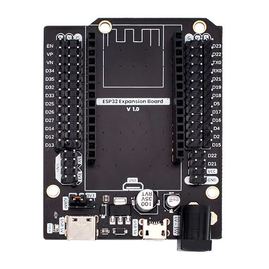
 Design with SHIELD BORNERA PARA ESP32 DE 30 PINES in Cirkit Designer
Introduction
The SHIELD BORNERA PARA ESP32 DE 30 PINES, manufactured by ESP32 (Part ID: BORNERA), is a 30-pin terminal shield designed to simplify the use of the ESP32 microcontroller. This shield provides easy access to the ESP32's GPIO pins via screw terminals, making it ideal for prototyping, testing, and connecting various sensors, actuators, and modules without the need for soldering.
Explore Projects Built with SHIELD BORNERA PARA ESP32 DE 30 PINES
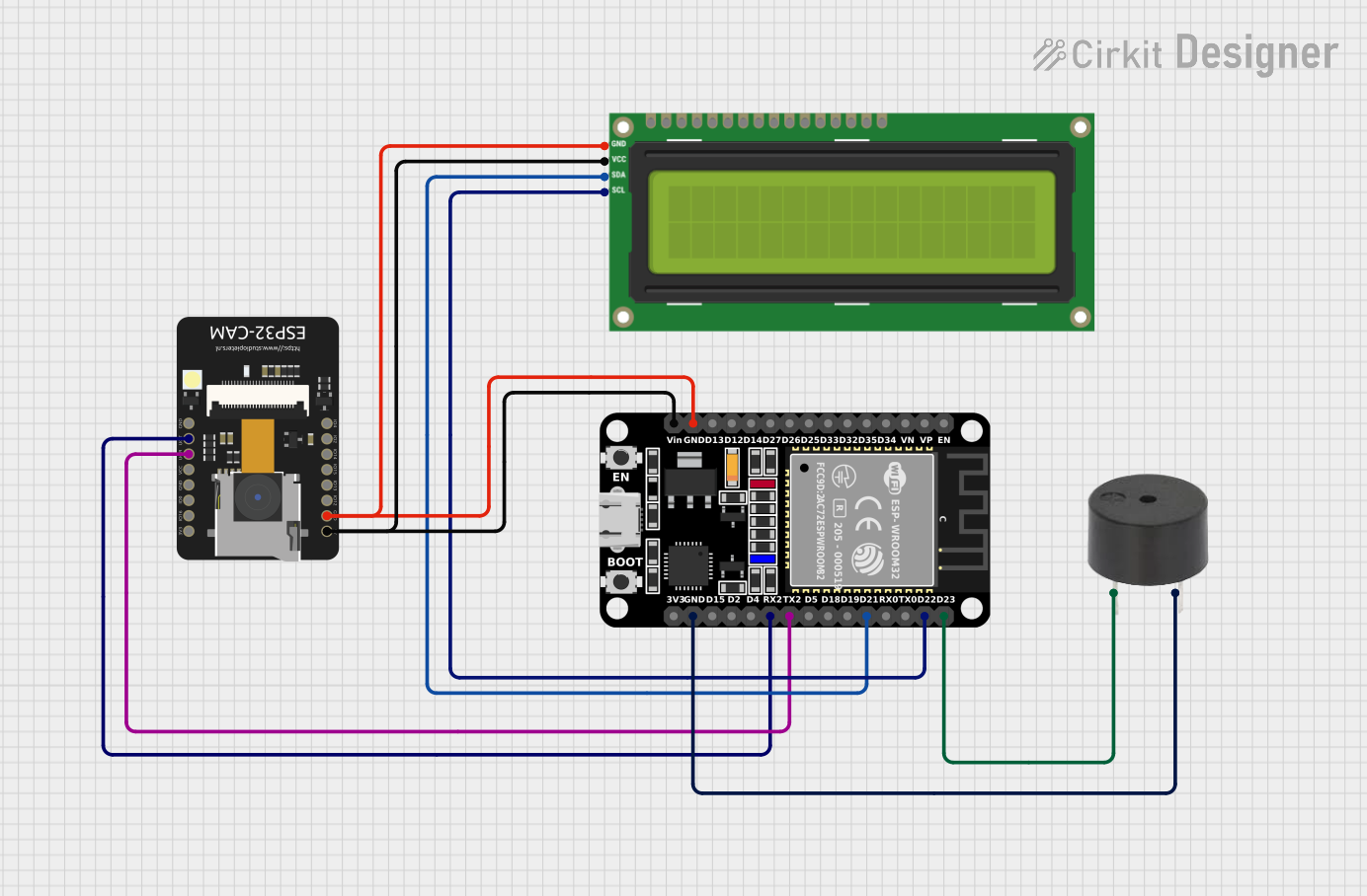 Open Project in Cirkit Designer
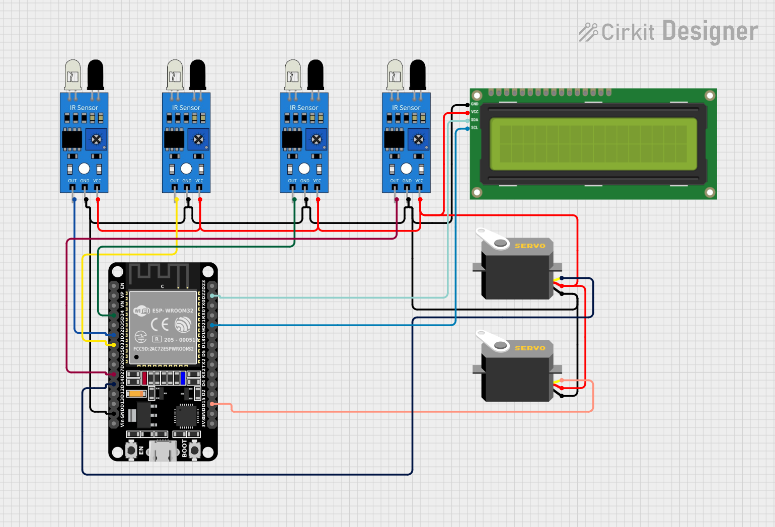 Open Project in Cirkit Designer
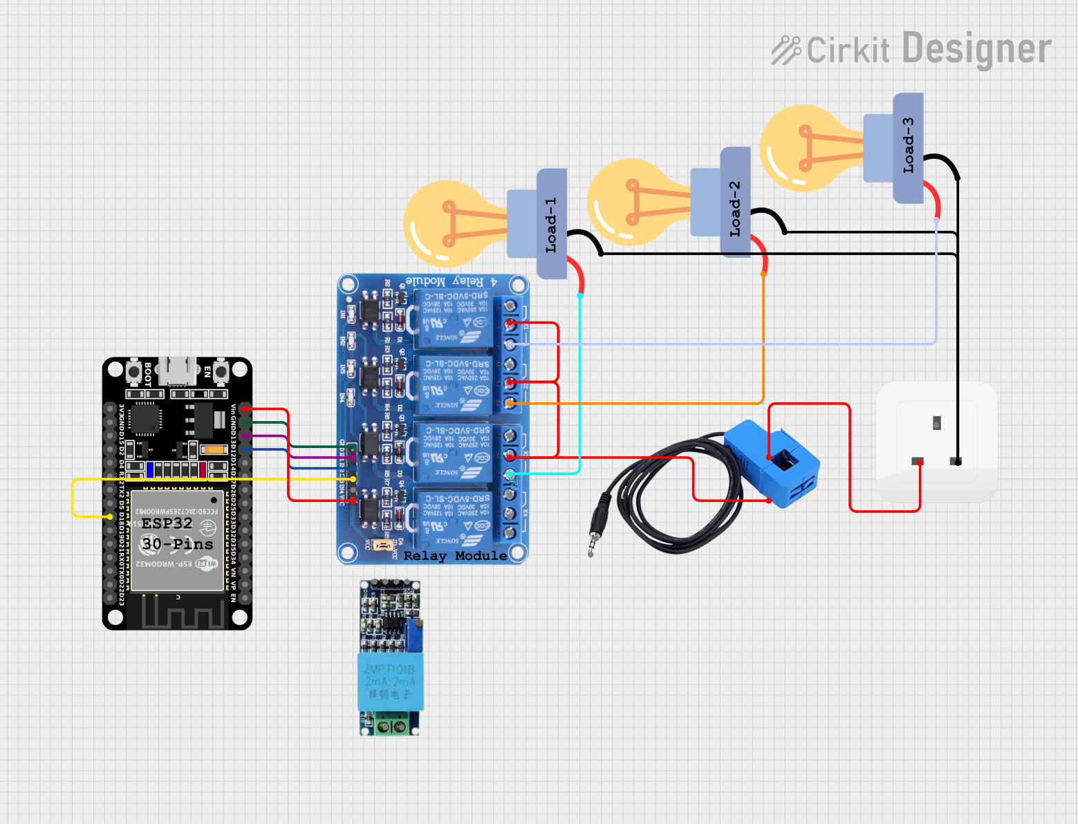 Open Project in Cirkit Designer
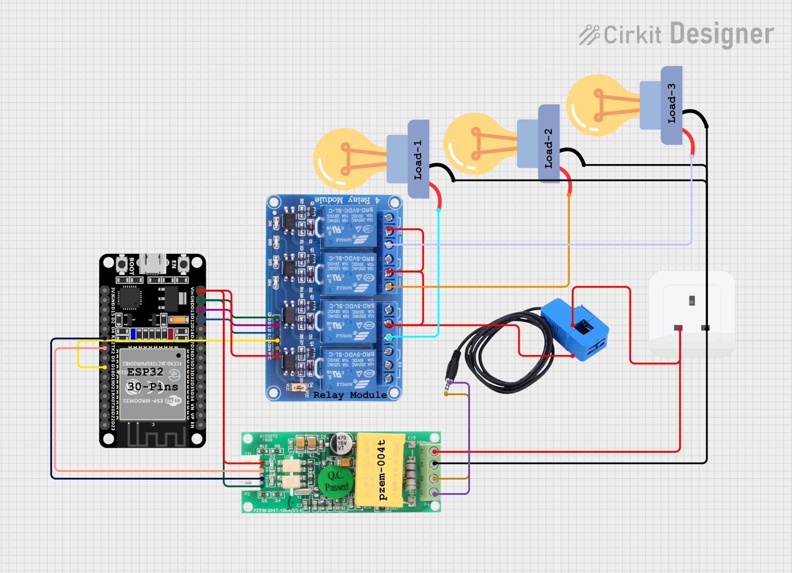 Open Project in Cirkit Designer
Explore Projects Built with SHIELD BORNERA PARA ESP32 DE 30 PINES
Open Project in Cirkit DesignerOpen Project in Cirkit DesignerOpen Project in Cirkit DesignerOpen Project in Cirkit DesignerCommon Applications and Use Cases
- Rapid prototyping of IoT devices
- Connecting sensors, relays, and actuators in industrial or home automation projects
- Educational projects requiring easy and secure wiring
- Testing and debugging ESP32-based circuits
Technical Specifications
Key Technical Details
- Compatibility: ESP32 microcontroller with 30 pins
- Number of Terminals: 30 screw terminals (1 per GPIO pin)
- Voltage Range: Supports 3.3V logic level (compatible with ESP32)
- Current Handling: Up to 2A per terminal
- Material: High-quality PCB with durable screw terminals
- Dimensions: Matches the ESP32 30-pin form factor
- Mounting: Directly mounts onto the ESP32 microcontroller
Pin Configuration and Descriptions
The SHIELD BORNERA provides a 1:1 mapping of the ESP32's GPIO pins to screw terminals. Below is the pin configuration:
| Pin Number | ESP32 Pin | Description |
|---|---|---|
| 1 | VIN | Input voltage (5V) |
| 2 | GND | Ground |
| 3 | GPIO36 | Analog input (ADC1_CH0) |
| 4 | GPIO39 | Analog input (ADC1_CH3) |
| 5 | GPIO34 | Analog input (ADC1_CH6) |
| 6 | GPIO35 | Analog input (ADC1_CH7) |
| 7 | GPIO32 | Analog input (ADC1_CH4) |
| 8 | GPIO33 | Analog input (ADC1_CH5) |
| 9 | GPIO25 | PWM output, DAC1 |
| 10 | GPIO26 | PWM output, DAC2 |
| 11 | GPIO27 | General-purpose I/O |
| 12 | GPIO14 | SPI clock (SCK) |
| 13 | GPIO12 | SPI MISO |
| 14 | GPIO13 | SPI MOSI |
| 15 | GPIO15 | General-purpose I/O |
| 16 | GPIO2 | General-purpose I/O |
| 17 | GPIO4 | General-purpose I/O |
| 18 | GPIO16 | UART RX |
| 19 | GPIO17 | UART TX |
| 20 | GPIO5 | General-purpose I/O |
| 21 | GPIO18 | SPI clock (SCK) |
| 22 | GPIO19 | SPI MISO |
| 23 | GPIO21 | I2C SDA |
| 24 | GPIO22 | I2C SCL |
| 25 | GPIO23 | SPI MOSI |
| 26 | EN | Enable pin |
| 27 | IO0 | Boot mode selection |
| 28 | IO3 | UART RX |
| 29 | IO1 | UART TX |
| 30 | GND | Ground |
Usage Instructions
How to Use the Component in a Circuit
- Mounting the Shield: Align the SHIELD BORNERA with the ESP32 microcontroller and gently press it into place. Ensure all pins are properly seated.
- Connecting Wires: Use a small screwdriver to loosen the screw terminals. Insert the wire into the terminal and tighten the screw to secure the connection.
- Powering the ESP32: Provide power to the ESP32 via the VIN and GND terminals or through the micro-USB port on the ESP32.
- Connecting Peripherals: Attach sensors, actuators, or other modules to the appropriate GPIO terminals based on your circuit design.
Important Considerations and Best Practices
- Voltage Levels: Ensure all connected peripherals operate at 3.3V logic levels to avoid damaging the ESP32.
- Current Limits: Do not exceed the 2A current rating per terminal.
- Pin Mapping: Double-check the pin mapping to avoid incorrect connections.
- Secure Connections: Tighten the screw terminals firmly to ensure reliable connections, but avoid overtightening to prevent damage.
Example Code for Arduino UNO-Compatible Setup
Below is an example of how to use the SHIELD BORNERA with an ESP32 to read a sensor value and control an LED:
// Example: Reading a sensor value and controlling an LED
const int sensorPin = 36; // GPIO36 (ADC1_CH0) connected to the sensor
const int ledPin = 25;    // GPIO25 connected to an LED

void setup() {
  pinMode(ledPin, OUTPUT); // Set LED pin as output
  Serial.begin(115200);    // Initialize serial communication
}

void loop() {
  int sensorValue = analogRead(sensorPin); // Read sensor value
  Serial.print("Sensor Value: ");
  Serial.println(sensorValue); // Print sensor value to Serial Monitor

  // Turn on LED if sensor value exceeds threshold
  if (sensorValue > 1000) {
    digitalWrite(ledPin, HIGH); // Turn on LED
  } else {
    digitalWrite(ledPin, LOW);  // Turn off LED
  }

  delay(500); // Wait for 500ms before next reading
}
Troubleshooting and FAQs
Common Issues Users Might Face
- Loose Connections: If the circuit is not functioning, check for loose wires in the screw terminals.
- Incorrect Pin Mapping: Ensure the correct GPIO pin is used for the intended function.
- Overcurrent Damage: Exceeding the current rating of 2A per terminal can damage the shield or ESP32.
Solutions and Tips for Troubleshooting
- Verify Connections: Double-check all connections against the pin configuration table.
- Test Individual Components: Test sensors and modules independently to ensure they are functioning correctly.
- Use a Multimeter: Measure voltage and current at the terminals to diagnose issues.
- Check Power Supply: Ensure the ESP32 is receiving adequate power (5V via VIN or USB).
By following this documentation, users can effectively utilize the SHIELD BORNERA PARA ESP32 DE 30 PINES for their projects, ensuring reliable and efficient connections to the ESP32 microcontroller.