How to Use LilyPad Coin Cell Battery Holder - Switched: Examples, Pinouts, and Specs
Introduction
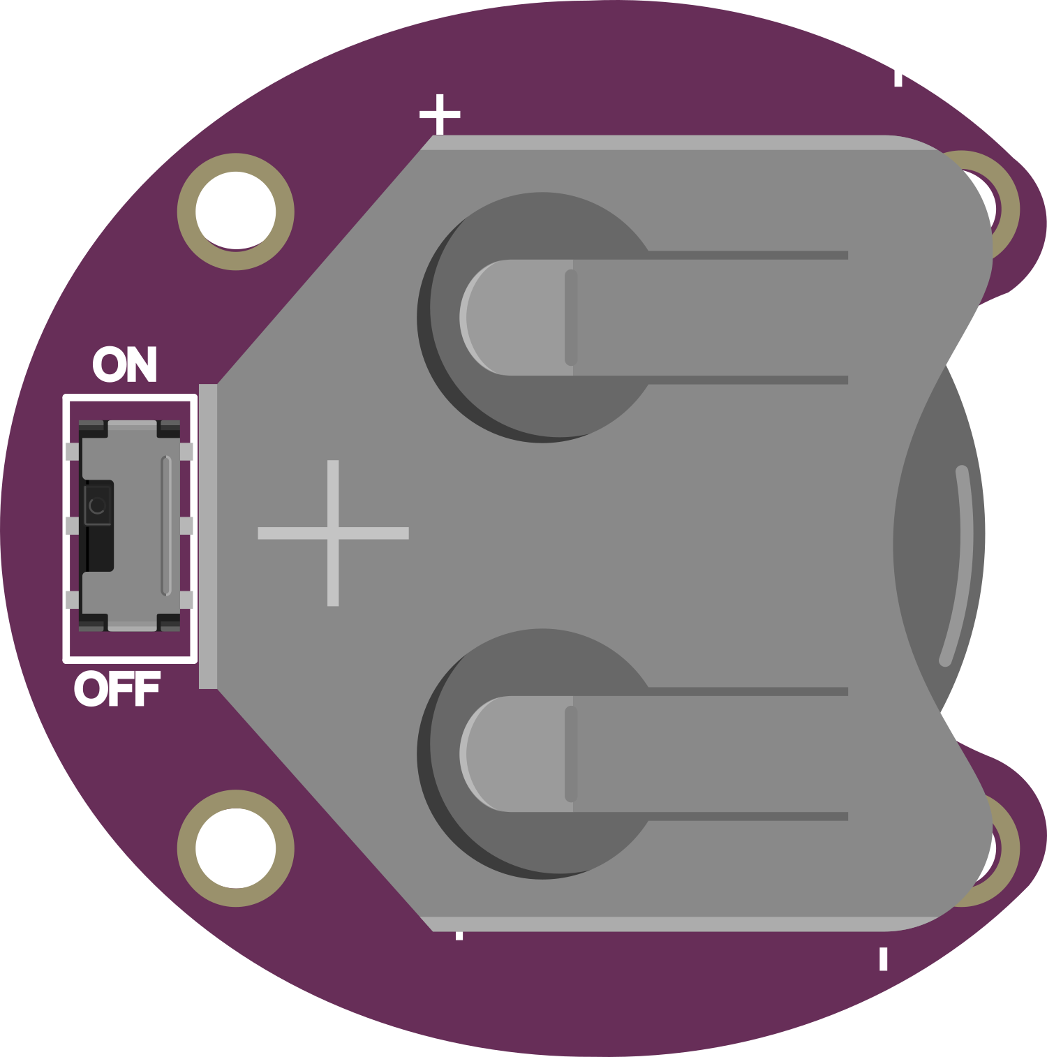
The LilyPad Coin Cell Battery Holder is a small, lightweight battery holder specifically designed for powering sewable electronic projects. It is part of the LilyPad wearable electronics ecosystem, which is a set of sewable electronic pieces designed to help you build soft, interactive textiles. This battery holder is equipped with an on/off switch, making power management convenient and straightforward. It is commonly used in wearable projects, soft circuits, and educational activities where portability and flexibility are essential.
Explore Projects Built with LilyPad Coin Cell Battery Holder - Switched
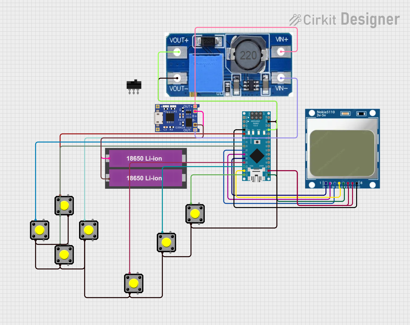

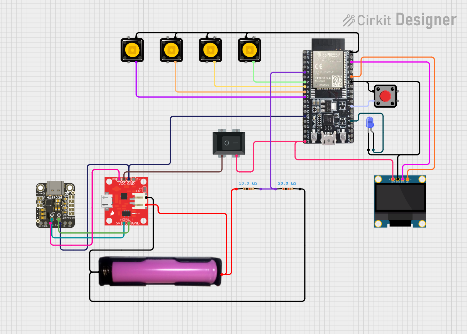
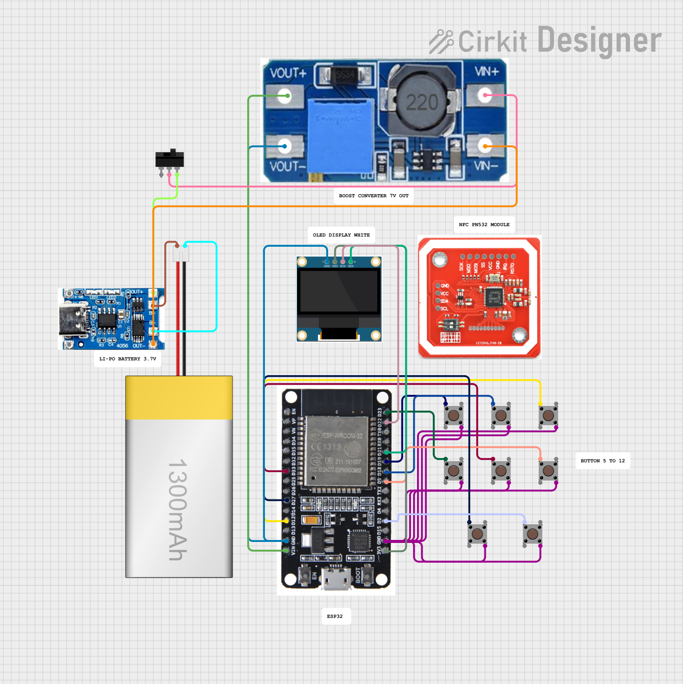
Explore Projects Built with LilyPad Coin Cell Battery Holder - Switched
Common Applications and Use Cases
- Wearable electronics (e.g., clothing, accessories)
- Educational projects and workshops
- Prototyping for soft circuits
- Interactive textile and fabric-based projects
Technical Specifications
Key Technical Details
- Voltage: 3V (typical for a CR2032 coin cell battery)
- Battery Type: CR2032 coin cell
- Maximum Battery Capacity: 20mm coin cell diameter
- Switch: Slide switch for power control
- Dimensions: 23mm outer diameter
- Sewing Tabs: 1+ positive and 1- negative large sew tabs for conductive thread
Pin Configuration and Descriptions
| Pin Name | Description |
|---|---|
+ |
Positive connection point for conductive thread |
- |
Negative connection point for conductive thread |
S |
Slide switch for turning the power on and off |
Usage Instructions
How to Use the Component in a Circuit
- Insert Battery: Open the battery holder and insert a CR2032 coin cell battery with the positive side facing up.
- Sewing: Use conductive thread to sew the
+tab to the positive points on your other LilyPad components and the-tab to the negative points. - Power Control: Use the slide switch to turn your project on and off. Ensure the switch is in the off position when inserting or removing the battery to avoid short circuits.
Important Considerations and Best Practices
- Conductive Thread: Ensure that the conductive thread does not touch itself or other conductive parts of the circuit as this can create short circuits.
- Battery Orientation: Always insert the battery with the correct orientation to prevent damage to the holder and the circuit.
- Storage: When not in use, switch the power off to conserve battery life.
- Insulation: If the back of the battery holder will be in contact with conductive material, insulate it with tape or fabric to prevent shorts.
Troubleshooting and FAQs
Common Issues
- Project Not Powering On: Check the battery orientation and ensure the switch is in the on position. Also, verify that the battery is not depleted.
- Intermittent Connections: Ensure that the conductive thread is securely sewn to the tabs and that there are no loose threads that could cause intermittent connections.
Solutions and Tips for Troubleshooting
- Secure Sewing: Double-check all connections and reinforce any loose stitches with additional conductive thread.
- Battery Replacement: If the battery is depleted, replace it with a new CR2032 coin cell battery.
- Inspection: Regularly inspect the circuit for wear and tear, especially if the project is subject to frequent movement or bending.
FAQs
Q: Can I wash my project with the LilyPad Coin Cell Battery Holder? A: Remove the battery before washing. Hand wash gently, avoiding heavy scrubbing on the electronic components. Do not machine wash.
Q: How long will the battery last? A: Battery life depends on the capacity of the CR2032 battery and the power consumption of your project. Typically, a CR2032 battery can last many hours or even days in low-power applications.
Q: Is the battery holder reusable? A: Yes, the battery holder is designed to be reusable. You can replace the battery as needed.
Q: Can I use a rechargeable coin cell battery with this holder? A: Yes, as long as the battery is the correct size (CR2032) and voltage (3V), it can be used with this holder.
Example Code for Arduino UNO
// Example code to blink an LED using a LilyPad Coin Cell Battery Holder
// connected to a LilyPad Arduino UNO.

const int ledPin = 13; // LED connected to digital pin 13

void setup() {
  pinMode(ledPin, OUTPUT); // Set the LED pin as an output
}

void loop() {
  digitalWrite(ledPin, HIGH); // Turn the LED on
  delay(1000);                // Wait for 1 second
  digitalWrite(ledPin, LOW);  // Turn the LED off
  delay(1000);                // Wait for 1 second
}
Remember to switch on the LilyPad Coin Cell Battery Holder before running the code. The above code will blink an onboard LED on the Arduino UNO, which is a simple test to ensure that your power supply from the LilyPad Coin Cell Battery Holder is functioning correctly.