How to Use VFD: Examples, Pinouts, and Specs
Introduction
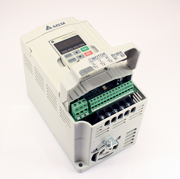
A Variable Frequency Drive (VFD) is an electronic device used to control the speed and torque of an electric motor by varying the frequency and voltage of its power supply. VFDs are essential in applications where precise motor control is required, such as in industrial automation, HVAC systems, and conveyor systems. By adjusting the motor speed, VFDs help in energy savings, reducing mechanical stress, and improving process control.
Explore Projects Built with VFD


Explore Projects Built with VFD
Technical Specifications
Key Technical Details
| Parameter | Value |
|---|---|
| Input Voltage | 200-240V AC (Single/Three Phase) |
| Output Voltage | 0-240V AC |
| Input Frequency | 50/60 Hz |
| Output Frequency | 0-400 Hz |
| Power Rating | 0.75 kW to 500 kW |
| Control Method | V/F Control, Vector Control |
| Overload Capacity | 150% for 1 minute |
| Protection | Overvoltage, Undervoltage, Overcurrent, Overtemperature |
Pin Configuration and Descriptions
| Pin Number | Pin Name | Description |
|---|---|---|
| 1 | R/L1 | Input Phase 1 |
| 2 | S/L2 | Input Phase 2 |
| 3 | T/L3 | Input Phase 3 |
| 4 | U/T1 | Output to Motor Phase 1 |
| 5 | V/T2 | Output to Motor Phase 2 |
| 6 | W/T3 | Output to Motor Phase 3 |
| 7 | GND | Ground |
| 8 | AI1 | Analog Input 1 (0-10V) |
| 9 | AI2 | Analog Input 2 (4-20mA) |
| 10 | DI1 | Digital Input 1 (Start/Stop) |
| 11 | DI2 | Digital Input 2 (Forward/Reverse) |
| 12 | DO1 | Digital Output 1 (Fault Indicator) |
| 13 | AO1 | Analog Output 1 (Frequency Output) |
| 14 | RS485+ | RS485 Communication Positive |
| 15 | RS485- | RS485 Communication Negative |
Usage Instructions
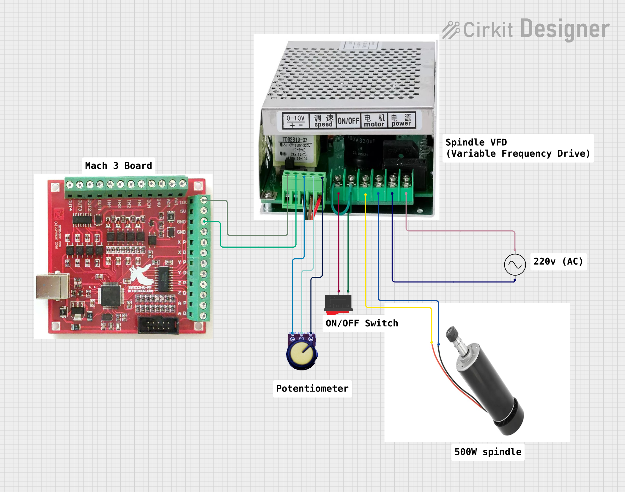
How to Use the VFD in a Circuit
Power Connection:
- Connect the input power supply to the R/L1, S/L2, and T/L3 terminals.
- Ensure the power supply matches the VFD's input voltage and frequency specifications.
Motor Connection:
- Connect the motor leads to the U/T1, V/T2, and W/T3 terminals.
- Verify the motor's voltage and current ratings are compatible with the VFD's output.
Control Wiring:
- Connect control signals to the appropriate analog and digital input terminals (AI1, AI2, DI1, DI2).
- Use the RS485 terminals for communication with external controllers or PLCs.
Grounding:
- Properly ground the VFD using the GND terminal to ensure safety and reduce electrical noise.
Important Considerations and Best Practices
Parameter Settings:
- Configure the VFD parameters according to the motor and application requirements. Refer to the VFD manual for detailed parameter settings.
Cooling:
- Ensure adequate ventilation and cooling for the VFD to prevent overheating. Follow the manufacturer's guidelines for installation.
EMI/RFI Mitigation:
- Use shielded cables for control wiring and follow proper grounding practices to minimize electromagnetic interference (EMI) and radio-frequency interference (RFI).
Regular Maintenance:
- Perform regular maintenance checks on the VFD and motor to ensure optimal performance and longevity.
Troubleshooting and FAQs
Common Issues and Solutions
VFD Not Powering On:
- Solution: Check the input power supply connections and ensure the voltage matches the VFD's specifications. Verify the fuses and circuit breakers are intact.
Motor Not Starting:
- Solution: Ensure the start command is given through the digital input (DI1). Check the motor connections and verify the VFD parameters are correctly set.
Overcurrent Fault:
- Solution: Inspect the motor for any mechanical obstructions. Verify the motor's current rating and adjust the VFD's current limit settings accordingly.
Overvoltage Fault:
- Solution: Check the input power supply for voltage spikes. Use a surge protector if necessary. Verify the deceleration time settings to prevent regenerative overvoltage.
FAQs
Q1: Can I use a VFD with any type of motor?
- A1: VFDs are typically used with three-phase induction motors. Ensure the motor's voltage and current ratings are compatible with the VFD.
Q2: How do I select the right VFD for my application?
- A2: Consider the motor's power rating, voltage, current, and the application's control requirements. Choose a VFD with appropriate specifications and features.
Q3: Can I control the VFD using an Arduino UNO?
- A3: Yes, you can control the VFD using an Arduino UNO through the analog or digital inputs. Below is an example code to control the VFD's speed using a potentiometer connected to the Arduino.
// Arduino code to control VFD speed using a potentiometer

const int potPin = A0; // Potentiometer connected to analog pin A0
const int vfdPin = 9;  // VFD analog input connected to PWM pin 9

void setup() {
  pinMode(vfdPin, OUTPUT); // Set the VFD pin as an output
}

void loop() {
  int potValue = analogRead(potPin); // Read the potentiometer value
  int vfdValue = map(potValue, 0, 1023, 0, 255); // Map the value to PWM range
  analogWrite(vfdPin, vfdValue); // Write the PWM value to the VFD
  delay(10); // Small delay for stability
}
This code reads the value from a potentiometer and maps it to a PWM signal, which is then sent to the VFD's analog input to control the motor speed.
By following this documentation, users can effectively utilize a VFD in their applications, ensuring proper installation, operation, and troubleshooting.