How to Use Pt1000 Temperature sensor: Examples, Pinouts, and Specs
Introduction
The Pt1000 temperature sensor is a type of Resistance Temperature Detector (RTD) that utilizes a platinum element with a resistance of 1000 ohms at 0°C. Known for its high accuracy and stability, the Pt1000 is widely used in industrial, scientific, and HVAC applications for precise temperature monitoring and control. Its linear resistance-temperature relationship makes it ideal for applications requiring reliable and repeatable temperature measurements.
Explore Projects Built with Pt1000 Temperature sensor

Explore Projects Built with Pt1000 Temperature sensor
Common Applications
- Industrial process control and monitoring
- HVAC systems for temperature regulation
- Laboratory and scientific research
- Food and beverage processing
- Medical equipment for temperature sensing
Technical Specifications
The Pt1000 sensor is designed to provide accurate temperature readings over a wide range of operating conditions. Below are its key technical details:
| Parameter | Value |
|---|---|
| Resistance at 0°C | 1000 Ω |
| Temperature Range | -200°C to +850°C |
| Tolerance Class | Class A or Class B (varies by model) |
| Temperature Coefficient | ~0.00385 Ω/Ω/°C |
| Material | Platinum |
| Accuracy | ±(0.15 + 0.002 × |
| Self-Heating Coefficient | ~0.4°C/mW (in still air) |
Pin Configuration and Descriptions
The Pt1000 sensor typically comes in a 2-wire, 3-wire, or 4-wire configuration. Below is a description of each configuration:
2-Wire Configuration
| Pin | Description |
|---|---|
| Pin 1 | Platinum element connection (1) |
| Pin 2 | Platinum element connection (2) |
3-Wire Configuration
| Pin | Description |
|---|---|
| Pin 1 | Platinum element connection (1) |
| Pin 2 | Platinum element connection (2) |
| Pin 3 | Compensation lead |
4-Wire Configuration
| Pin | Description |
|---|---|
| Pin 1 | Platinum element connection (1) |
| Pin 2 | Platinum element connection (2) |
| Pin 3 | Compensation lead (1) |
| Pin 4 | Compensation lead (2) |
Usage Instructions
How to Use the Pt1000 in a Circuit
- Choose the Configuration: Determine whether a 2-wire, 3-wire, or 4-wire configuration is required based on the desired accuracy and application.
- For high-accuracy applications, use a 3-wire or 4-wire configuration to compensate for lead resistance.
- Connect to a Measurement Circuit: The Pt1000 sensor requires a current source and a voltage measurement circuit to determine resistance. Use a precision resistor and an operational amplifier for accurate readings.
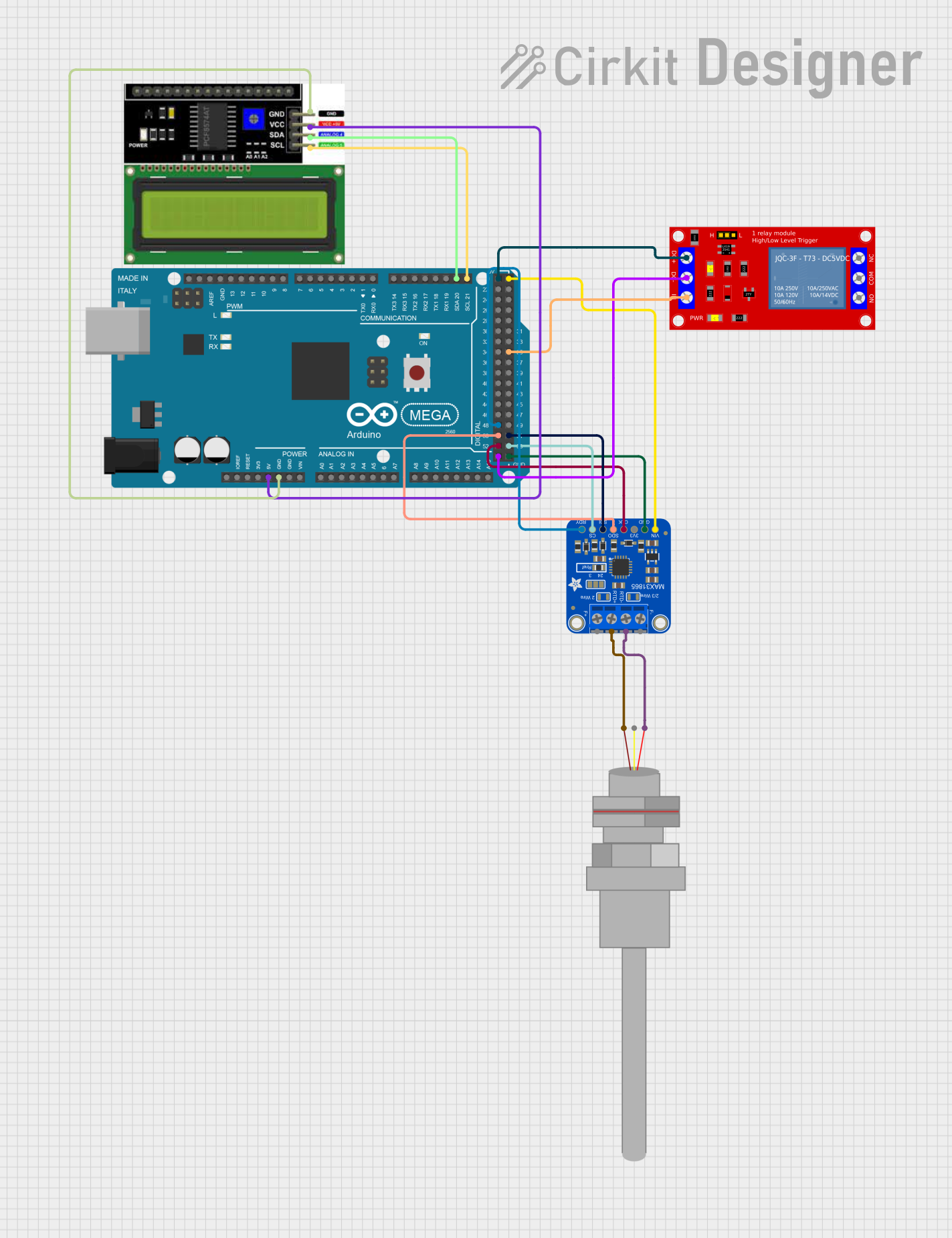
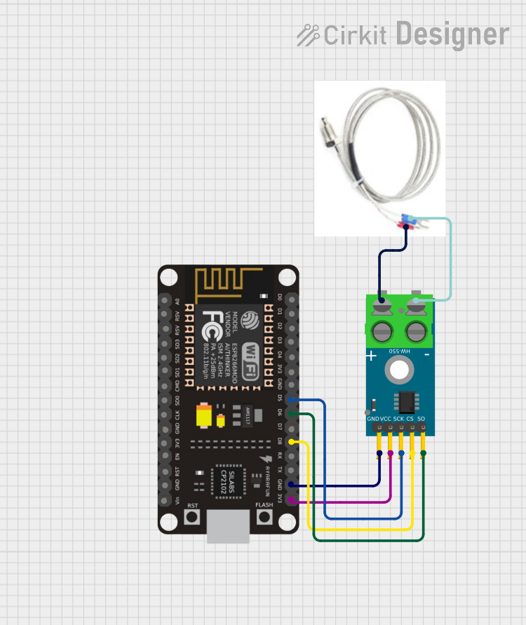
- Interface with a Microcontroller: To interface with a microcontroller like an Arduino UNO, use an analog-to-digital converter (ADC) to measure the voltage across the sensor. A Wheatstone bridge circuit can also be used for better accuracy.
Example Arduino Code
Below is an example of how to interface a Pt1000 sensor with an Arduino UNO using a simple voltage divider circuit:
// Pt1000 Temperature Sensor Example with Arduino UNO
// This code reads the voltage from the Pt1000 sensor and calculates the temperature.

const int sensorPin = A0; // Analog pin connected to the voltage divider
const float R_ref = 1000.0; // Reference resistor value in ohms
const float T0 = 0.0; // Reference temperature in °C
const float R0 = 1000.0; // Resistance of Pt1000 at 0°C in ohms
const float alpha = 0.00385; // Temperature coefficient of Pt1000

void setup() {
  Serial.begin(9600); // Initialize serial communication
}

void loop() {
  int sensorValue = analogRead(sensorPin); // Read analog value
  float voltage = sensorValue * (5.0 / 1023.0); // Convert to voltage
  float R_pt1000 = (R_ref * voltage) / (5.0 - voltage); // Calculate sensor resistance

  // Calculate temperature using the linear approximation formula
  float temperature = (R_pt1000 - R0) / (R0 * alpha);

  // Print the temperature to the Serial Monitor
  Serial.print("Temperature: ");
  Serial.print(temperature);
  Serial.println(" °C");

  delay(1000); // Wait 1 second before the next reading
}
Important Considerations
- Self-Heating: Minimize the current through the Pt1000 to reduce self-heating effects, which can cause measurement errors.
- Lead Resistance: For long cable runs, use a 3-wire or 4-wire configuration to compensate for lead resistance.
- Calibration: Periodically calibrate the sensor to maintain accuracy, especially in critical applications.
- Environmental Protection: Use appropriate enclosures or coatings to protect the sensor in harsh environments.
Troubleshooting and FAQs
Common Issues
Inaccurate Temperature Readings
- Cause: Lead resistance not compensated.
- Solution: Use a 3-wire or 4-wire configuration to eliminate lead resistance effects.
Fluctuating Readings
- Cause: Electrical noise or unstable power supply.
- Solution: Add decoupling capacitors and ensure a stable power source.
Sensor Damage
- Cause: Exposure to extreme temperatures or physical damage.
- Solution: Verify the operating temperature range and handle the sensor carefully.
Self-Heating Effects
- Cause: Excessive current through the sensor.
- Solution: Limit the current to a safe value (typically 1 mA or less).
FAQs
Can the Pt1000 be used with any microcontroller?
- Yes, as long as the microcontroller has an ADC and the appropriate interface circuitry.
What is the difference between Pt100 and Pt1000 sensors?
- The Pt1000 has a resistance of 1000 ohms at 0°C, while the Pt100 has 100 ohms. The Pt1000 is less affected by lead resistance, making it more suitable for long cable runs.
How do I protect the sensor in corrosive environments?
- Use a protective sheath or coating, such as stainless steel or Teflon, to shield the sensor.
What is the maximum cable length for a Pt1000 sensor?
- The maximum length depends on the configuration and application. For long distances, use a 3-wire or 4-wire setup to minimize errors.