How to Use IRLZ34N: Examples, Pinouts, and Specs
Introduction
The IRLZ34N is an N-channel MOSFET (Metal-Oxide-Semiconductor Field-Effect Transistor) designed for high-speed switching applications. It is known for its low on-resistance (RDS(on)), which ensures efficient power management and minimal energy loss. This component is widely used in circuits requiring high current handling and fast switching capabilities.
Explore Projects Built with IRLZ34N

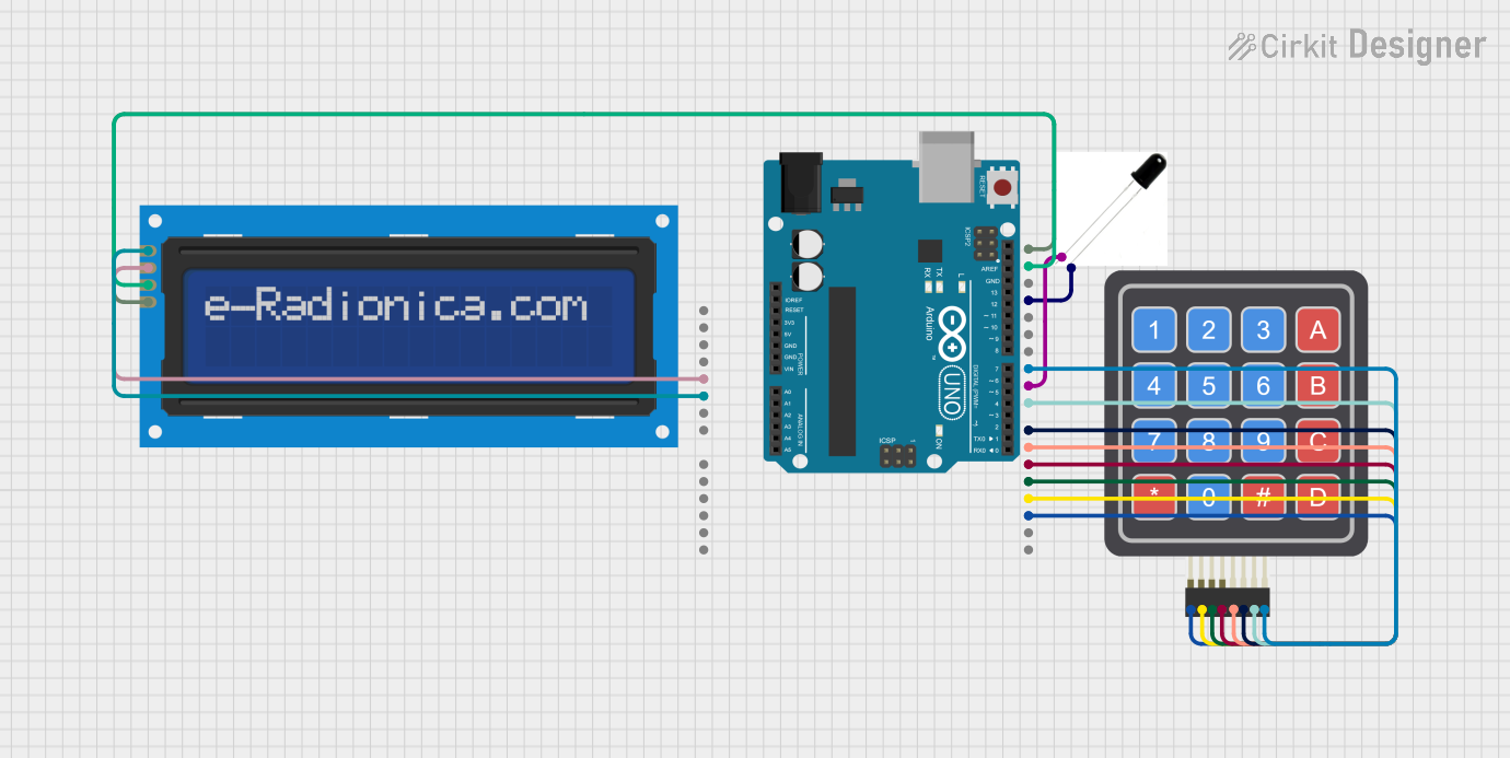
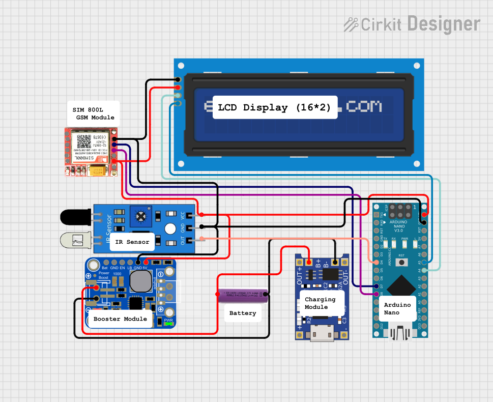
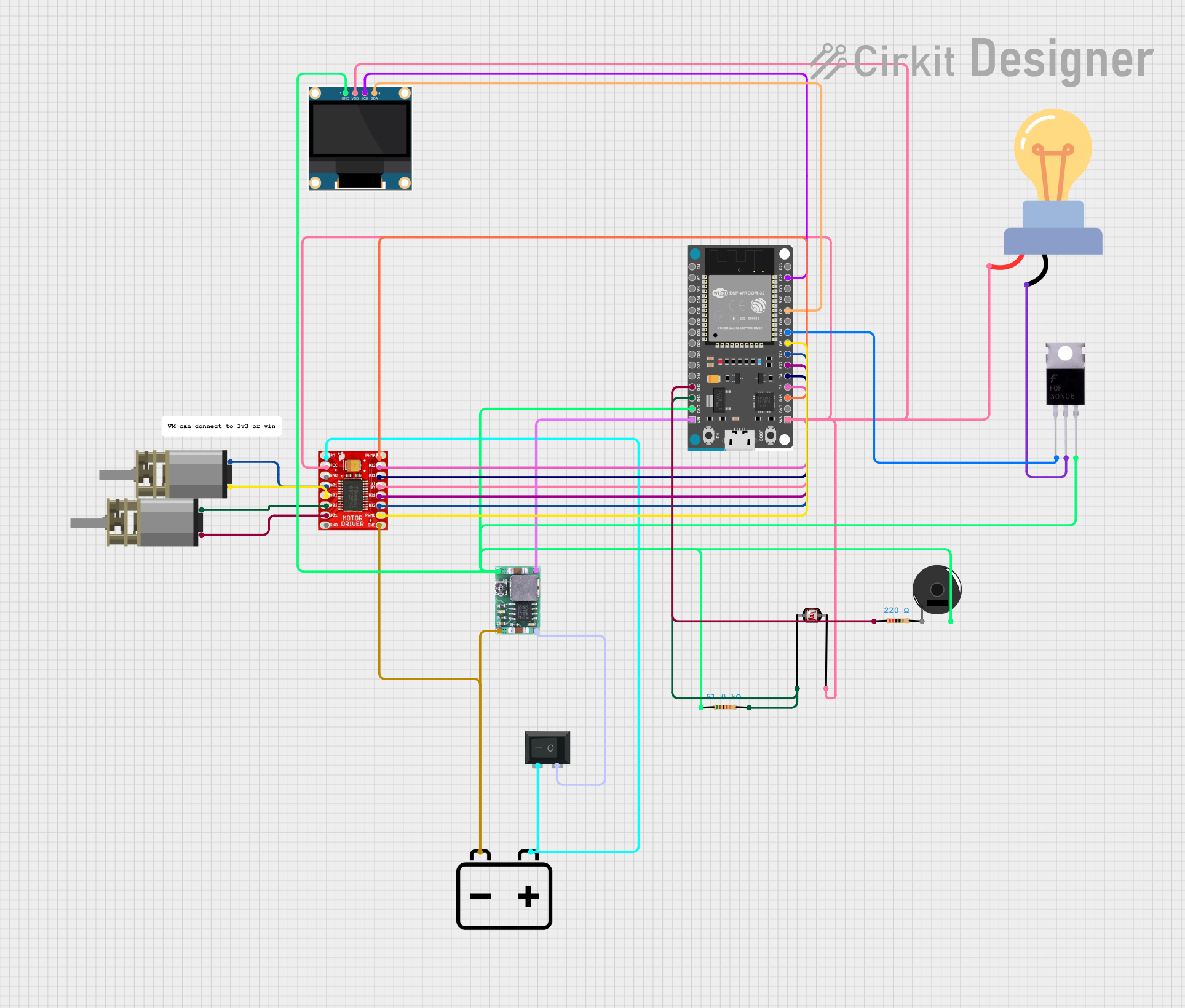
Explore Projects Built with IRLZ34N
Common Applications
- Power supplies and voltage regulation
- Motor control and driver circuits
- LED lighting systems
- Battery management systems
- DC-DC converters
- General-purpose switching in high-current applications
Technical Specifications
Below are the key technical details of the IRLZ34N MOSFET:
| Parameter | Value |
|---|---|
| Type | N-Channel MOSFET |
| Maximum Drain-Source Voltage (VDS) | 55V |
| Maximum Gate-Source Voltage (VGS) | ±16V |
| Continuous Drain Current (ID) @ 25°C | 30A |
| Pulsed Drain Current (IDM) | 110A |
| On-Resistance (RDS(on)) @ VGS = 5V | 0.035Ω |
| Total Gate Charge (Qg) | 67nC |
| Power Dissipation (PD) | 68W |
| Operating Temperature Range | -55°C to +175°C |
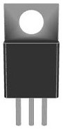
| Package Type | TO-220 |
Pin Configuration
The IRLZ34N is housed in a TO-220 package with three pins. The pinout is as follows:
| Pin Number | Pin Name | Description |
|---|---|---|
| 1 | Gate (G) | Controls the MOSFET's switching state |
| 2 | Drain (D) | Current flows into this pin |
| 3 | Source (S) | Current flows out of this pin |
Usage Instructions
How to Use the IRLZ34N in a Circuit
- Gate Control: Apply a voltage to the Gate (G) to control the MOSFET's switching state. A voltage of 5V or higher is typically sufficient to fully turn on the IRLZ34N.
- Drain-Source Current Flow: When the Gate is activated, current flows from the Drain (D) to the Source (S). Ensure the current does not exceed the maximum rating of 30A.
- Heat Dissipation: Use a heatsink with the TO-220 package to manage heat dissipation, especially in high-current applications.
- Protection: Add a flyback diode across inductive loads (e.g., motors) to protect the MOSFET from voltage spikes.
Example Circuit with Arduino UNO
The IRLZ34N can be used to control a DC motor with an Arduino UNO. Below is an example circuit and code:
Circuit Connections
- Gate (G): Connect to an Arduino digital pin (e.g., D9) through a 220Ω resistor.
- Drain (D): Connect to one terminal of the motor.
- Source (S): Connect to ground (GND).
- The other terminal of the motor connects to the positive supply voltage (e.g., 12V).
- Add a flyback diode (e.g., 1N4007) across the motor terminals to protect the MOSFET.
Arduino Code
// Example code to control a DC motor using the IRLZ34N MOSFET
// The motor is connected to pin D9 of the Arduino UNO

const int motorPin = 9; // Define the pin connected to the MOSFET Gate

void setup() {
  pinMode(motorPin, OUTPUT); // Set the motor pin as an output
}

void loop() {
  analogWrite(motorPin, 128); // Set motor speed to 50% (PWM value: 128)
  delay(5000);               // Run motor for 5 seconds

  analogWrite(motorPin, 0);  // Turn off the motor
  delay(5000);               // Wait for 5 seconds
}
Best Practices
- Use a pull-down resistor (e.g., 10kΩ) on the Gate pin to ensure the MOSFET remains off when no signal is applied.
- Avoid exceeding the maximum voltage and current ratings to prevent damage.
- Ensure proper grounding and minimize noise in the circuit for reliable operation.
Troubleshooting and FAQs
Common Issues and Solutions
MOSFET Not Turning On
- Ensure the Gate voltage is at least 5V for full activation.
- Check for loose or incorrect connections in the circuit.
Excessive Heat
- Verify that the current through the MOSFET does not exceed 30A.
- Use a heatsink to dissipate heat effectively.
Motor Not Running
- Check the flyback diode orientation and ensure it is properly connected.
- Verify the PWM signal from the Arduino is functioning correctly.
MOSFET Damage
- Ensure the Gate-Source voltage does not exceed ±16V.
- Protect the MOSFET from voltage spikes using appropriate components (e.g., TVS diodes).
FAQs
Q: Can the IRLZ34N be used with 3.3V logic?
A: The IRLZ34N is optimized for 5V logic levels. While it may partially turn on with 3.3V, it is recommended to use a logic-level MOSFET specifically designed for 3.3V operation.
Q: What is the purpose of the flyback diode?
A: The flyback diode protects the MOSFET from voltage spikes generated by inductive loads, such as motors or relays, during switching.
Q: Can I use the IRLZ34N for AC applications?
A: The IRLZ34N is primarily designed for DC applications. For AC applications, consider using a TRIAC or other suitable components.
Q: How do I calculate the required heatsink size?
A: Use the formula P = I2 × RDS(on) to calculate power dissipation, then select a heatsink with adequate thermal resistance to maintain safe operating temperatures.