How to Use PZEM-04T: Examples, Pinouts, and Specs
Introduction
The PZEM-04T is a multifunctional energy meter designed for monitoring and measuring key electrical parameters in AC circuits. It can measure voltage, current, power, energy consumption, and frequency, making it an essential tool for energy management and monitoring systems. The module features a UART interface for seamless communication with microcontrollers, enabling data logging and remote monitoring applications. Its compact design and high accuracy make it suitable for a wide range of applications.
Explore Projects Built with PZEM-04T


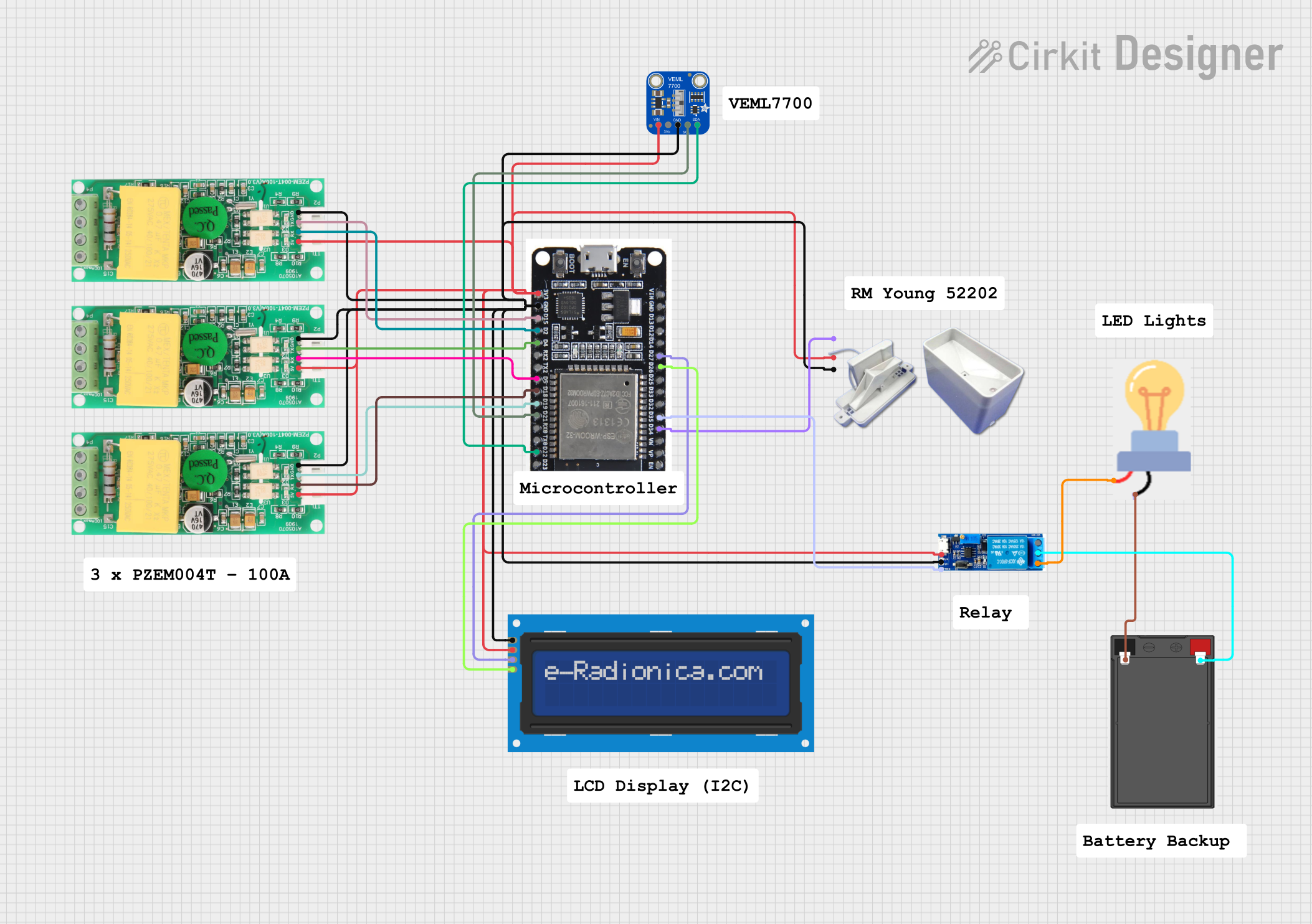
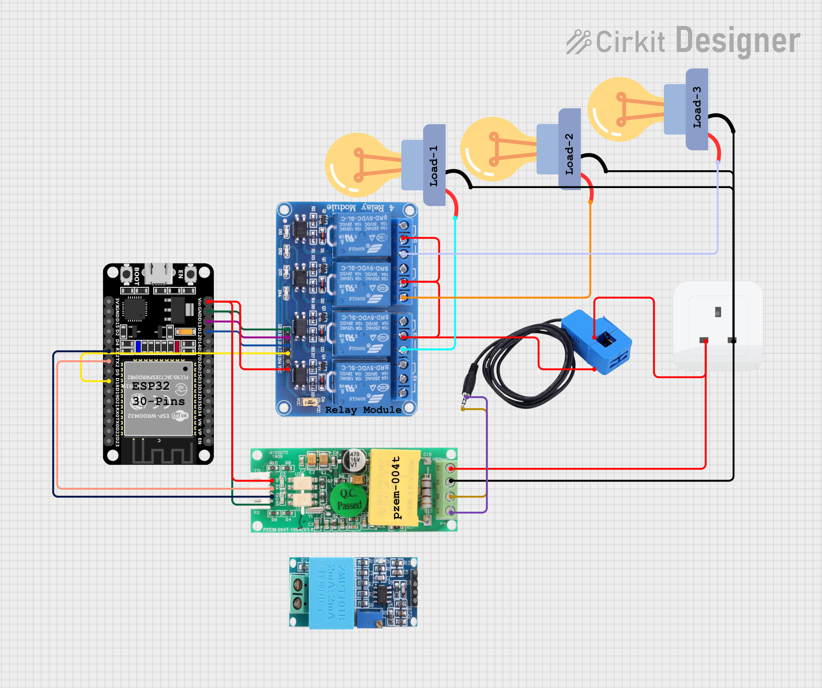
Explore Projects Built with PZEM-04T
Common Applications
- Home energy monitoring systems
- Industrial equipment monitoring
- Renewable energy systems (e.g., solar inverters)
- IoT-based energy management solutions
- Laboratory testing and prototyping
Technical Specifications
Key Specifications
| Parameter | Value |
|---|---|
| Voltage Range | 80V - 260V AC |
| Current Range | 0A - 100A (with external CT) |
| Power Range | 0W - 22kW |
| Energy Range | 0kWh - 9999kWh |
| Frequency Range | 45Hz - 65Hz |
| Communication | UART (9600 baud rate) |
| Power Supply | Self-powered (via AC input) |
| Accuracy | ±0.5% |
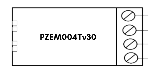
Pin Configuration
The PZEM-04T module has a 4-pin interface for communication and power connections. Below is the pin configuration:
| Pin Number | Pin Name | Description |
|---|---|---|
| 1 | VCC | Power supply for the UART interface (5V) |
| 2 | GND | Ground connection |
| 3 | RX | UART Receive pin (connect to TX of MCU) |
| 4 | TX | UART Transmit pin (connect to RX of MCU) |
Usage Instructions
Connecting the PZEM-04T
- Power Supply: The module is self-powered through the AC input, but the UART interface requires a 5V power supply connected to the
VCCandGNDpins. - Current Transformer (CT): Connect the external CT to the module's designated input. Ensure the CT is clamped around the live wire of the AC circuit.
- UART Communication: Connect the
RXpin of the PZEM-04T to theTXpin of your microcontroller (e.g., Arduino UNO) and theTXpin of the PZEM-04T to theRXpin of the microcontroller.
Example Arduino Code
Below is an example of how to interface the PZEM-04T with an Arduino UNO to read voltage, current, and power:
#include <SoftwareSerial.h>

// Define RX and TX pins for SoftwareSerial
SoftwareSerial pzemSerial(10, 11); // RX = Pin 10, TX = Pin 11

// PZEM-04T communication commands
byte readVoltage[] = {0xB0, 0xC0, 0xA8, 0x01, 0x01, 0x00, 0x1A};
byte response[7];

void setup() {
  Serial.begin(9600);          // Initialize Serial Monitor
  pzemSerial.begin(9600);      // Initialize PZEM-04T communication
  Serial.println("PZEM-04T Test");
}

void loop() {
  // Send command to read voltage
  pzemSerial.write(readVoltage, sizeof(readVoltage));
  delay(100); // Wait for response

  // Read response from PZEM-04T
  if (pzemSerial.available() >= 7) {
    for (int i = 0; i < 7; i++) {
      response[i] = pzemSerial.read();
    }

    // Calculate voltage from response
    float voltage = (response[3] << 8 | response[4]) / 10.0;
    Serial.print("Voltage: ");
    Serial.print(voltage);
    Serial.println(" V");
  }

  delay(1000); // Wait 1 second before next reading
}
Important Considerations
- Safety: Ensure proper insulation and handling when working with high-voltage AC circuits.
- CT Orientation: The current transformer must be clamped in the correct orientation for accurate readings.
- Baud Rate: The UART communication operates at a fixed baud rate of 9600. Ensure your microcontroller is configured accordingly.
- Data Parsing: The PZEM-04T sends data in a specific format. Refer to the datasheet for detailed communication protocols.
Troubleshooting and FAQs
Common Issues
No Data Received via UART
- Cause: Incorrect wiring or baud rate mismatch.
- Solution: Verify the
RXandTXconnections and ensure the baud rate is set to 9600.
Inaccurate Readings
- Cause: Improper CT installation or loose connections.
- Solution: Ensure the CT is securely clamped around the live wire and verify all connections.
Module Not Powering On
- Cause: No AC input or faulty module.
- Solution: Check the AC input voltage and ensure it is within the specified range (80V - 260V AC).
FAQs
Q: Can the PZEM-04T measure DC circuits?
A: No, the PZEM-04T is designed specifically for AC circuits and cannot measure DC parameters.
Q: Can I use multiple PZEM-04T modules with a single microcontroller?
A: Yes, but each module must have a unique address. Refer to the datasheet for instructions on setting module addresses.
Q: What is the maximum distance for UART communication?
A: The maximum reliable distance for UART communication is typically around 15 meters. For longer distances, consider using RS485 converters.
This concludes the documentation for the PZEM-04T module. For further details, refer to the official datasheet or contact the manufacturer.