How to Use PAM8403: Examples, Pinouts, and Specs
Introduction
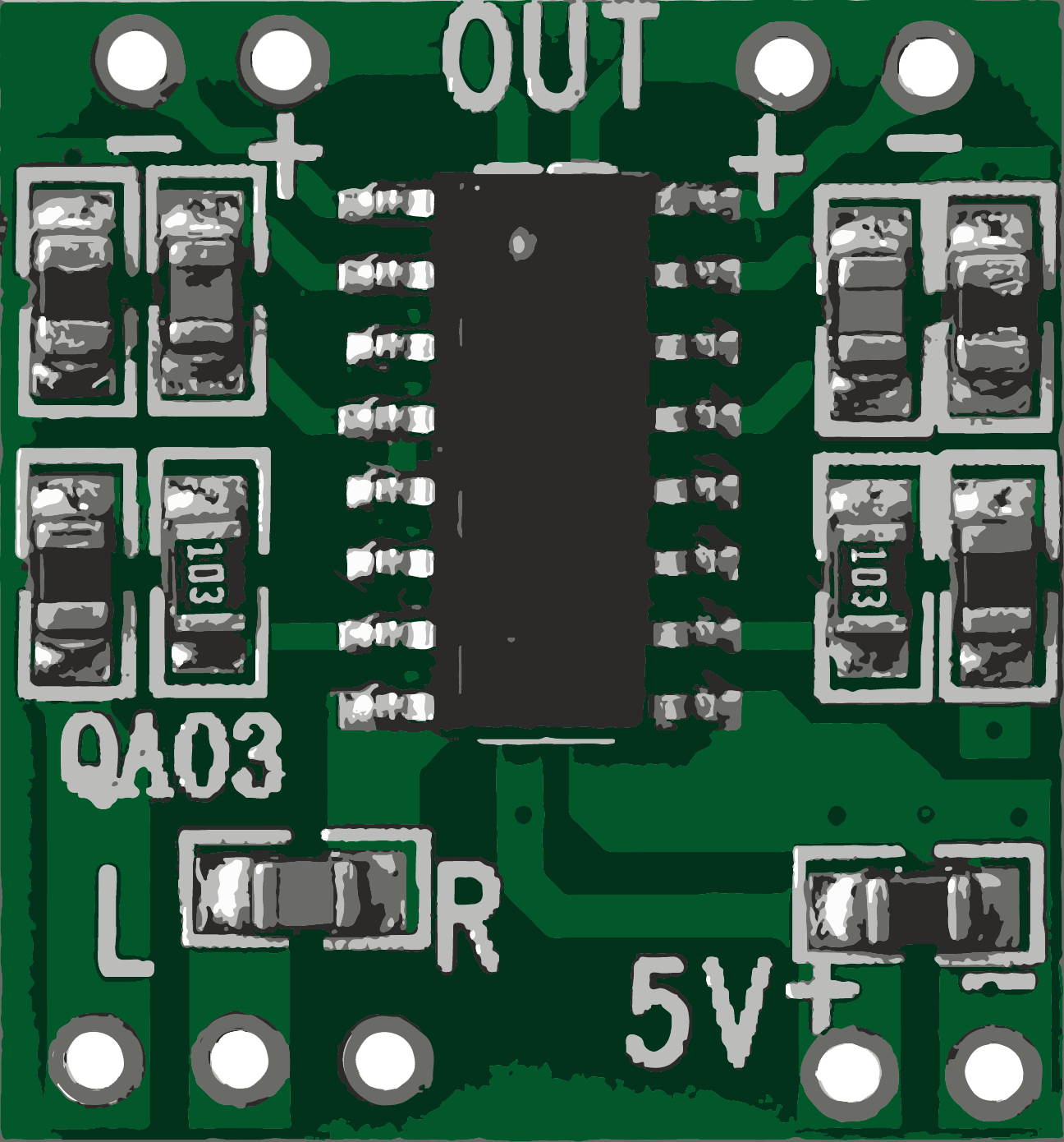
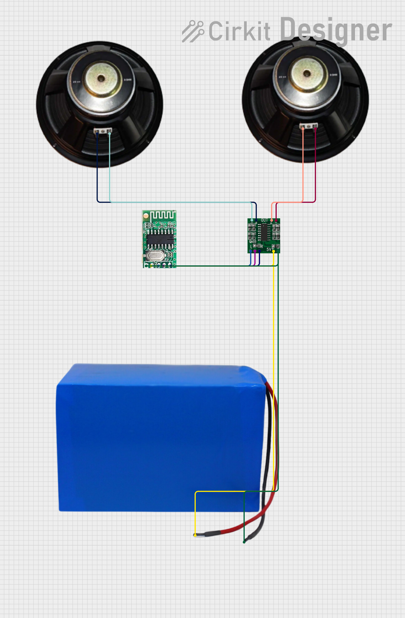
The PAM8403 is a small digital amplifier chip that offers high-quality stereo audio amplification. It is widely used in portable devices due to its low power consumption and minimal heat generation. The PAM8403 is capable of driving 3W+3W output with excellent sound quality and efficiency, making it an ideal choice for battery-powered applications, DIY audio projects, and any system where space is at a premium and sound quality is important.
Explore Projects Built with PAM8403
Explore Projects Built with PAM8403
Common Applications and Use Cases
- Portable speakers
- DIY audio amplifiers
- Battery-powered audio devices
- Desktop computer speakers
- MP3/MP4 players
Technical Specifications
Key Technical Details
- Supply Voltage: 2.5V to 5.5V DC
- Output Power: 3W+3W (6W total) at 4Ω with 5V supply
- Efficiency: >90%
- Signal-to-Noise Ratio (SNR): 90dB
- Total Harmonic Distortion (THD): <0.1%
- Channels: Two (stereo output)
- Class: Class D
Pin Configuration and Descriptions
| Pin Number | Pin Name | Description |
|---|---|---|
| 1 | VDD | Power supply (2.5V to 5.5V) |
| 2 | GND | Ground |
| 3 | L_IN | Left channel audio input |
| 4 | R_IN | Right channel audio input |
| 5 | L_OUT+ | Left channel positive audio output |
| 6 | L_OUT- | Left channel negative audio output |
| 7 | R_OUT+ | Right channel positive audio output |
| 8 | R_OUT- | Right channel negative audio output |
| 9 | SD | Shutdown control input (active low) |
| 10 | MUTE | Mute control input (active low) |
Usage Instructions
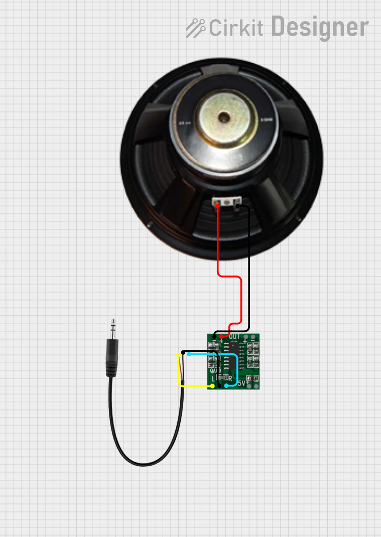
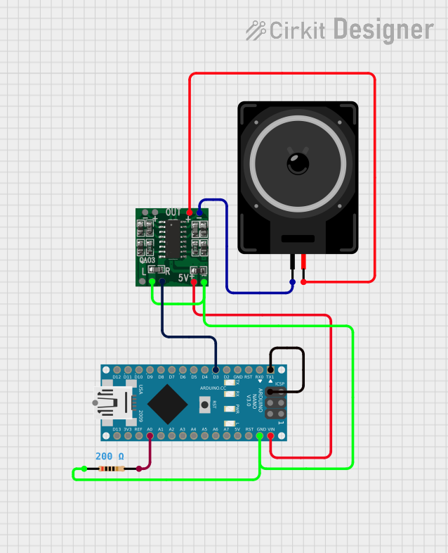
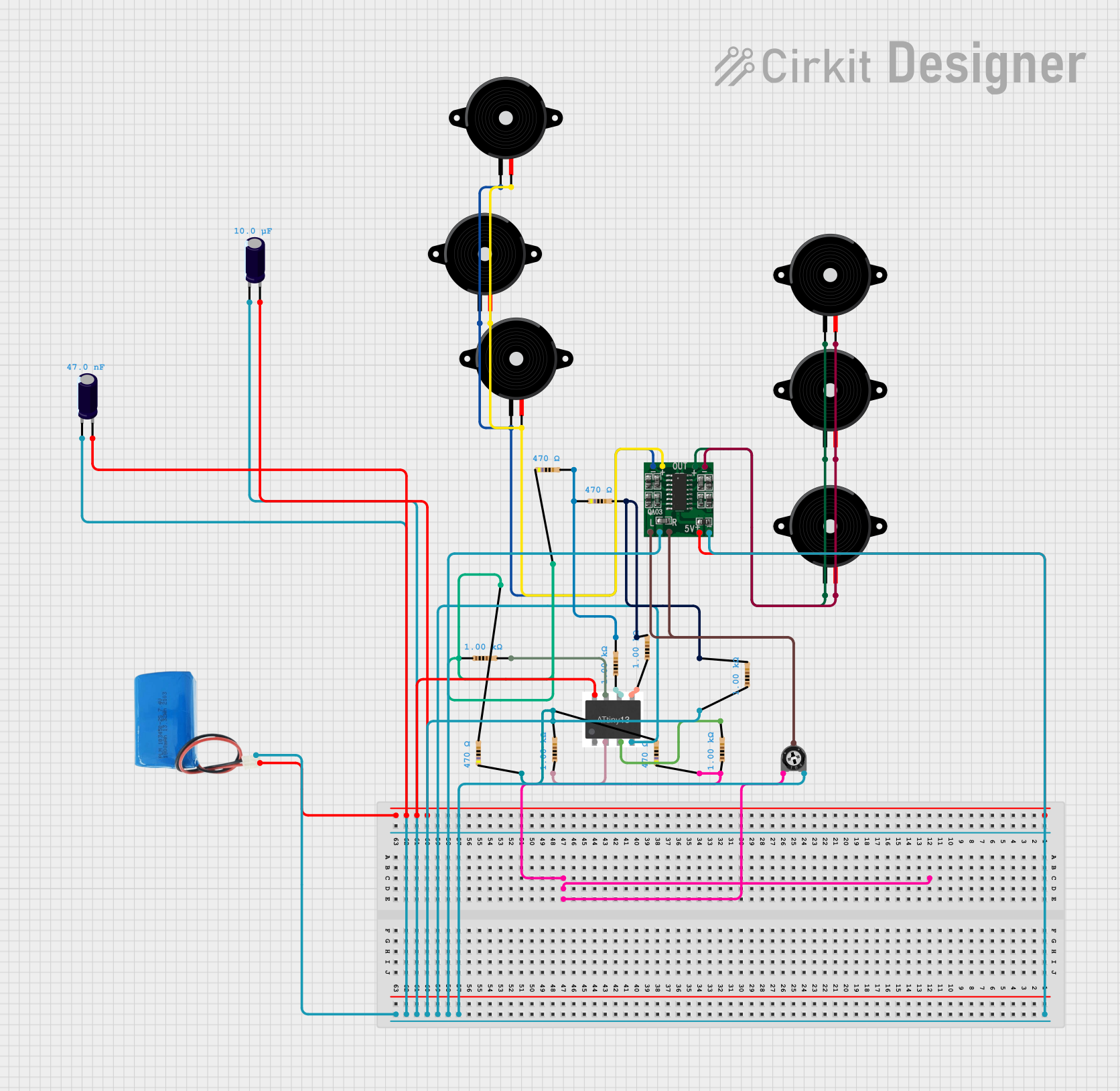
How to Use the PAM8403 in a Circuit
Power Supply: Connect a clean DC power supply between the VDD and GND pins. Ensure that the voltage is within the specified range (2.5V to 5.5V).
Audio Input: Connect the left and right audio input sources to the L_IN and R_IN pins, respectively.
Audio Output: Connect the speakers to the L_OUT+/- and R_OUT+/- pins. Note that the PAM8403 does not require an output filter when used with inductive loads (speakers).
Shutdown and Mute: The SD and MUTE pins can be left unconnected if not used. To use these features, connect them to a microcontroller or switch to control the shutdown and mute functions.
Important Considerations and Best Practices
- Use a clean power supply to minimize noise in the audio output.
- Place a 1µF capacitor between the VDD and GND pins to stabilize the power supply.
- Keep audio input lines as short as possible to reduce the risk of picking up interference.
- Ensure that the speakers' impedance matches the recommended load (typically 4Ω).
- Avoid short-circuiting the output terminals.
- Provide adequate ventilation to prevent overheating during prolonged use.
Troubleshooting and FAQs
Common Issues
- No Sound Output: Check power supply connections and ensure that the SD and MUTE pins are not inadvertently activated.
- Distorted Sound: Ensure that the power supply voltage is within the specified range and that the input signal is not too high, causing clipping.
- Overheating: Make sure that the module is not enclosed in a tight space without ventilation, and that the speaker impedance is not too low.
Solutions and Tips for Troubleshooting
- Verify all connections and ensure that solder joints are solid and not shorting.
- Test the power supply with a multimeter to confirm the voltage is within the specified range.
- Use a pre-amplifier if the input signal is too weak.
- If using the shutdown or mute functions, ensure that the control signals are correctly implemented.
FAQs
Q: Can I use the PAM8403 with 8Ω speakers? A: Yes, the PAM8403 can drive 8Ω speakers, but the output power will be lower compared to using 4Ω speakers.
Q: What is the maximum input voltage for the audio signal? A: The maximum input voltage should not exceed the supply voltage to avoid distortion.
Q: Can I use a single power supply for both the PAM8403 and an Arduino? A: Yes, as long as the power supply is within the voltage range for both devices and can provide sufficient current.
Example Arduino Connection and Code
// Example code to control the PAM8403 mute function with an Arduino UNO

const int mutePin = 3; // Connect to the MUTE pin of the PAM8403

void setup() {
  pinMode(mutePin, OUTPUT);
  digitalWrite(mutePin, HIGH); // Start with the amplifier unmuted
}

void loop() {
  // Mute the amplifier for 2 seconds
  digitalWrite(mutePin, LOW);
  delay(2000);

  // Unmute the amplifier
  digitalWrite(mutePin, HIGH);
  delay(2000);
}
Note: This code example demonstrates how to control the mute function of the PAM8403 using an Arduino digital pin. The mutePin should be connected to the MUTE pin on the PAM8403, and the Arduino must share a common ground with the amplifier module.