
How to Use ESP32-S3 AI Camera: Examples, Pinouts, and Specs
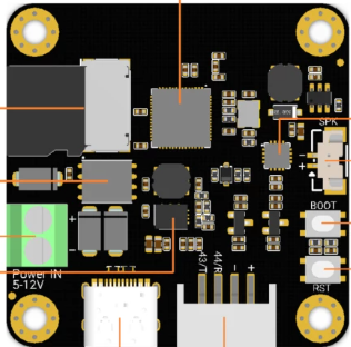
 Design with ESP32-S3 AI Camera in Cirkit Designer
Introduction
The ESP32-S3 AI Camera (DFR1154), manufactured by DF Robot, is a powerful AI-enabled camera module built around the ESP32-S3 chip. This module integrates Wi-Fi and Bluetooth capabilities, making it ideal for advanced image processing and machine learning applications. It is designed to handle tasks such as facial recognition, object detection, and other AI-driven image analysis tasks.
Explore Projects Built with ESP32-S3 AI Camera
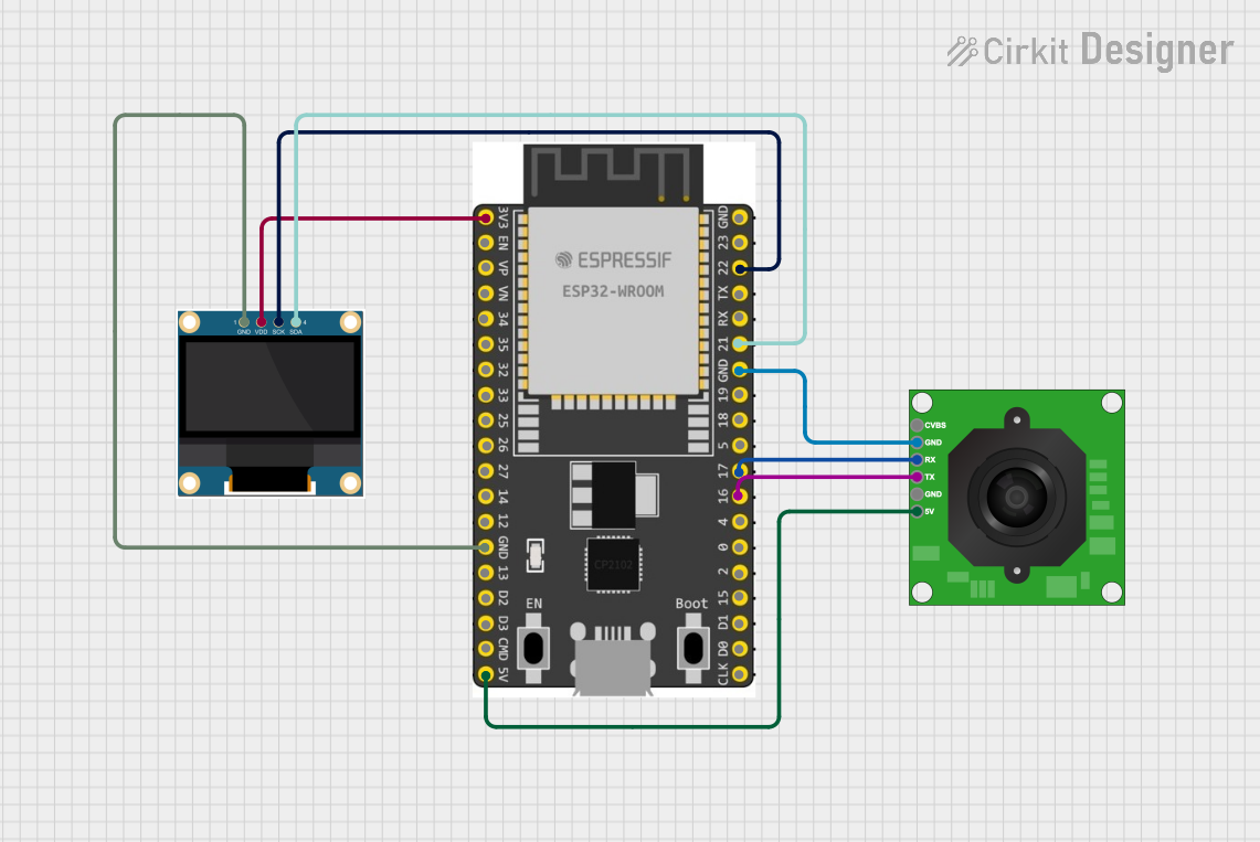 Open Project in Cirkit Designer
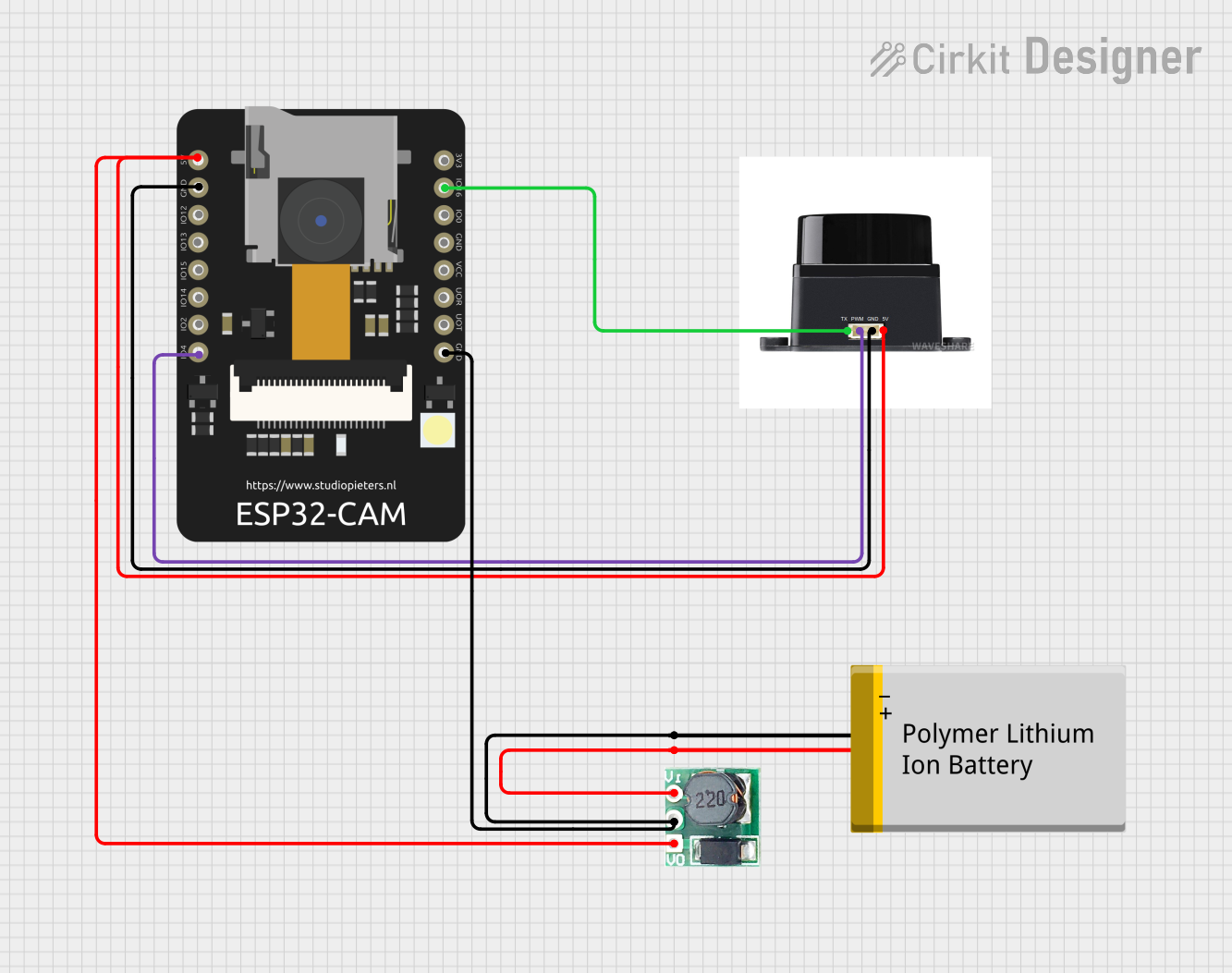 Open Project in Cirkit Designer
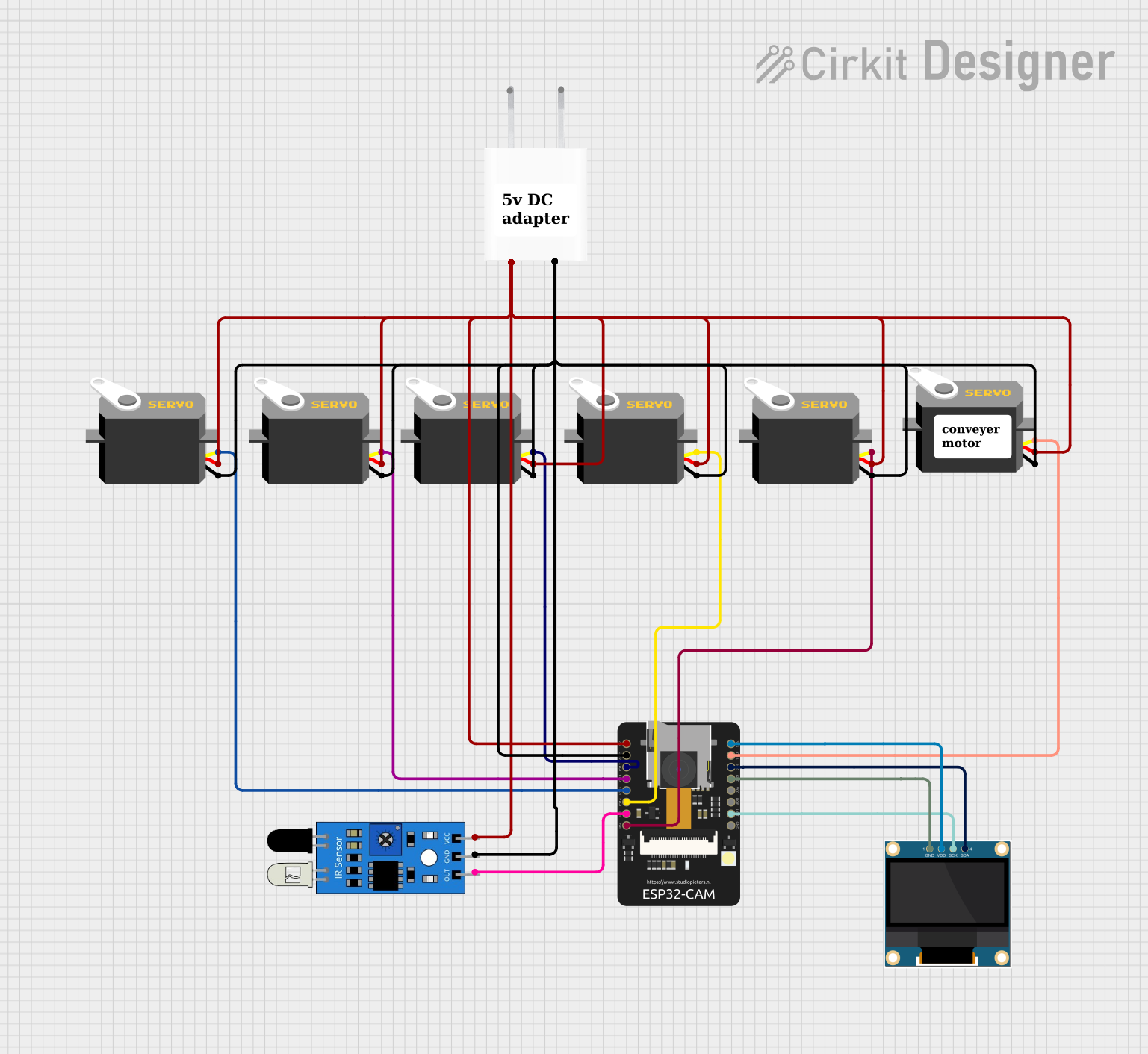 Open Project in Cirkit Designer
 Open Project in Cirkit Designer
Explore Projects Built with ESP32-S3 AI Camera
Open Project in Cirkit DesignerOpen Project in Cirkit DesignerOpen Project in Cirkit DesignerOpen Project in Cirkit DesignerCommon Applications and Use Cases
- Smart home automation (e.g., facial recognition for door locks)
- AI-powered surveillance systems
- Object detection and tracking
- Edge computing for IoT devices
- Educational projects involving AI and computer vision
- Robotics and autonomous systems
Technical Specifications
Key Technical Details
| Parameter | Specification |
|---|---|
| Microcontroller | ESP32-S3 (Xtensa® 32-bit LX7 dual-core processor) |
| Camera Sensor | OV2640 (2MP resolution) |
| Wireless Connectivity | Wi-Fi 802.11 b/g/n and Bluetooth 5.0 |
| Flash Memory | 8MB PSRAM + 16MB Flash |
| Operating Voltage | 3.3V |
| Power Consumption | ~240mA (active mode) |
| Interfaces | I2C, SPI, UART, GPIO, ADC, PWM |
| Dimensions | 40mm x 30mm |
| Operating Temperature | -40°C to 85°C |
Pin Configuration and Descriptions
The ESP32-S3 AI Camera module features a 24-pin interface. Below is the pinout and description:
| Pin Number | Pin Name | Description |
|---|---|---|
| 1 | GND | Ground |
| 2 | 3V3 | 3.3V Power Supply |
| 3 | GPIO0 | General Purpose I/O (Boot Mode Selection) |
| 4 | GPIO1 | General Purpose I/O |
| 5 | GPIO2 | General Purpose I/O |
| 6 | GPIO3 | General Purpose I/O |
| 7 | TXD0 | UART0 Transmit |
| 8 | RXD0 | UART0 Receive |
| 9 | SDA | I2C Data Line |
| 10 | SCL | I2C Clock Line |
| 11 | MISO | SPI Master-In-Slave-Out |
| 12 | MOSI | SPI Master-Out-Slave-In |
| 13 | SCK | SPI Clock |
| 14 | CS | SPI Chip Select |
| 15 | ADC1 | Analog Input Channel 1 |
| 16 | ADC2 | Analog Input Channel 2 |
| 17 | PWM1 | Pulse Width Modulation Output 1 |
| 18 | PWM2 | Pulse Width Modulation Output 2 |
| 19 | RST | Reset Pin |
| 20 | EN | Enable Pin (Power On/Off Control) |
| 21 | CAM_D0 | Camera Data Line 0 |
| 22 | CAM_D1 | Camera Data Line 1 |
| 23 | CAM_PCLK | Camera Pixel Clock |
| 24 | CAM_VSYNC | Camera Vertical Sync |
Usage Instructions
How to Use the ESP32-S3 AI Camera in a Circuit
- Power Supply: Connect the 3.3V pin to a regulated 3.3V power source and GND to ground.
- Camera Initialization: Ensure the OV2640 camera sensor is properly connected to the ESP32-S3 module.
- Communication Interfaces: Use UART, I2C, or SPI for communication with external devices or microcontrollers.
- Programming: The module can be programmed using the Arduino IDE or ESP-IDF (Espressif IoT Development Framework).
- Wi-Fi and Bluetooth: Configure the wireless connectivity for remote data transmission or control.
Important Considerations and Best Practices
- Power Supply: Ensure a stable 3.3V power source to avoid damage to the module.
- Boot Mode: Use GPIO0 to select the boot mode. Pull it LOW during programming.
- Heat Management: The ESP32-S3 may heat up during intensive tasks. Consider adding a heatsink if necessary.
- Camera Lens: Avoid touching the camera lens to prevent smudges or scratches that could affect image quality.
- Firmware Updates: Regularly update the firmware to access the latest features and bug fixes.
Example Code for Arduino UNO Integration
Below is an example of how to use the ESP32-S3 AI Camera with an Arduino UNO for basic image capture and Wi-Fi transmission:
#include <WiFi.h>
#include <esp_camera.h>

// Replace with your Wi-Fi credentials
const char* ssid = "Your_SSID";
const char* password = "Your_PASSWORD";

void setup() {
  Serial.begin(115200);

  // Initialize Wi-Fi
  WiFi.begin(ssid, password);
  while (WiFi.status() != WL_CONNECTED) {
    delay(500);
    Serial.print(".");
  }
  Serial.println("\nWi-Fi connected!");

  // Initialize the camera
  camera_config_t config;
  config.ledc_channel = LEDC_CHANNEL_0;
  config.ledc_timer = LEDC_TIMER_0;
  config.pin_d0 = CAM_D0;
  config.pin_d1 = CAM_D1;
  config.pin_xclk = CAM_PCLK;
  config.pin_vsync = CAM_VSYNC;
  config.pixel_format = PIXFORMAT_JPEG; // Set image format to JPEG
  config.frame_size = FRAMESIZE_QVGA;   // Set frame size to QVGA (320x240)

  if (!esp_camera_init(&config)) {
    Serial.println("Camera initialized successfully!");
  } else {
    Serial.println("Camera initialization failed!");
    while (1);
  }
}

void loop() {
  // Capture an image
  camera_fb_t* fb = esp_camera_fb_get();
  if (!fb) {
    Serial.println("Failed to capture image");
    return;
  }

  // Send image data over Serial (or Wi-Fi)
  Serial.write(fb->buf, fb->len);

  // Free the frame buffer
  esp_camera_fb_return(fb);

  delay(5000); // Capture an image every 5 seconds
}
Troubleshooting and FAQs
Common Issues and Solutions
Camera Initialization Fails:
- Ensure the camera sensor is properly connected to the ESP32-S3 module.
- Verify that the camera pins are correctly configured in the code.
Wi-Fi Connection Issues:
- Double-check the SSID and password in your code.
- Ensure the Wi-Fi network is within range and operational.
Overheating:
- If the module overheats during operation, reduce the workload or add a heatsink.
Image Quality Problems:
- Clean the camera lens to remove smudges or dirt.
- Adjust the camera settings (e.g., resolution, brightness) in the code.
FAQs
Q: Can the ESP32-S3 AI Camera be powered by a 5V source?
A: No, the module requires a regulated 3.3V power supply. Using 5V may damage the module.
Q: Is the module compatible with Arduino IDE?
A: Yes, the ESP32-S3 AI Camera can be programmed using the Arduino IDE with the appropriate ESP32 board package installed.
Q: Can I use this module for real-time video streaming?
A: Yes, the ESP32-S3 AI Camera supports real-time video streaming over Wi-Fi, but performance may vary depending on the resolution and frame rate.
Q: How do I update the firmware?
A: Firmware updates can be performed using the ESP-IDF or Arduino IDE via the USB interface.
Q: What is the maximum resolution supported by the camera?
A: The OV2640 camera sensor supports a maximum resolution of 1600x1200 (UXGA).