How to Use 12 V Fan: Examples, Pinouts, and Specs
12 V Fan Documentation
1. Introduction
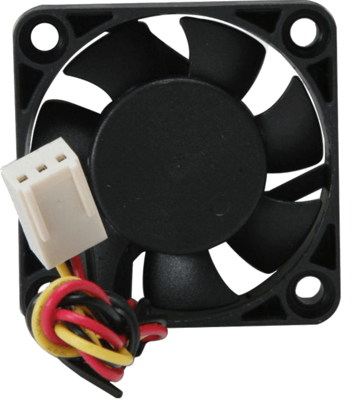
The 12 V Fan (Manufacturer: Fan, Part ID: 12 V Fan) is a compact and efficient electric fan designed to operate on a 12-volt DC power supply. It is widely used in applications requiring effective cooling, ventilation, or airflow management. This fan is ideal for cooling electronic devices, improving airflow in enclosures, or providing ventilation in small spaces.
Common Applications:
- Cooling computer components (e.g., CPUs, GPUs, power supplies)
- Ventilation in electronic enclosures or cabinets
- Air circulation in 3D printers, robotics, and DIY projects
- Cooling for power amplifiers, battery packs, or other heat-generating devices
- General-purpose ventilation in small spaces
2. Technical Specifications
The following table outlines the key technical details of the 12 V Fan:
| Parameter | Value |
|---|---|
| Operating Voltage | 12 V DC |
| Operating Current | 0.1 A to 0.5 A (varies by model) |
| Power Consumption | 1.2 W to 6 W |
| Fan Speed | 2000–5000 RPM (varies by model) |
| Airflow | 20–50 CFM (Cubic Feet per Minute) |
| Noise Level | 20–40 dBA |
| Dimensions | 80 mm x 80 mm x 25 mm (typical) |
| Connector Type | 2-pin or 3-pin (depending on model) |
| Bearing Type | Sleeve or Ball Bearing |
| Operating Temperature | -10°C to 70°C |
| Lifespan | 30,000–50,000 hours |
Pin Configuration and Descriptions
| Pin | Name | Description |
|---|---|---|
| 1 | VCC (+) | Positive power supply input (12 V DC). Connect to the 12 V power source. |
| 2 | GND (-) | Ground connection. Connect to the ground of the power source or circuit. |
| 3* | Tachometer | (Optional) Provides a signal for fan speed monitoring. Available on 3-pin models. |
*Note: The tachometer pin is only available on 3-pin fan models. It outputs a pulse signal proportional to the fan's speed.
3. Usage Instructions
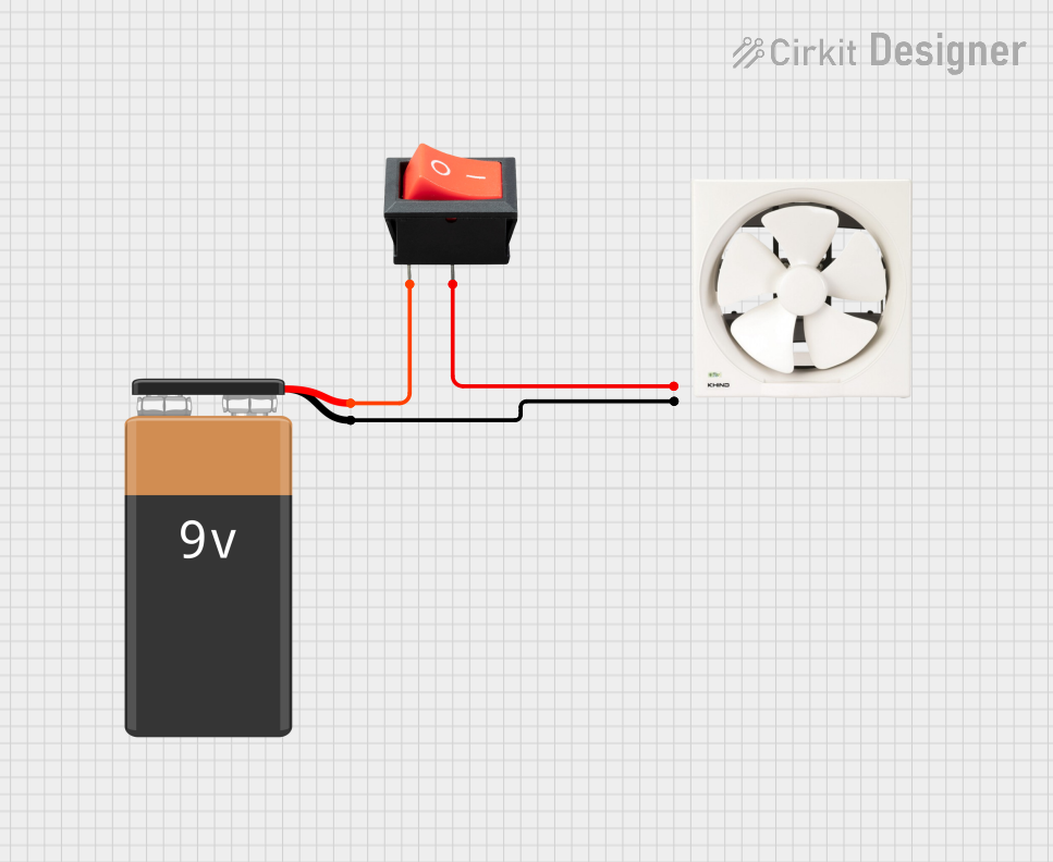
Connecting the 12 V Fan to a Circuit
- Power Supply: Ensure you have a 12 V DC power source capable of supplying sufficient current for the fan (e.g., 0.5 A for high-speed models).
- Wiring:
- Connect the VCC (+) pin of the fan to the positive terminal of the 12 V power supply.
- Connect the GND (-) pin of the fan to the ground terminal of the power supply.
- If using a 3-pin fan, connect the Tachometer pin to a microcontroller or monitoring circuit for speed feedback (optional).
- Mounting: Secure the fan in place using screws or adhesive mounts. Ensure proper airflow direction (indicated by arrows on the fan housing).
Important Considerations:
- Polarity: Always connect the fan with the correct polarity. Reversing the connections may damage the fan.
- Voltage: Do not exceed the rated 12 V DC input. Overvoltage can cause overheating or permanent damage.
- Airflow Direction: Check the airflow direction (usually marked on the fan housing) to ensure proper cooling or ventilation.
- Noise: If noise is a concern, consider using a fan with a lower RPM or a ball-bearing design for quieter operation.
- PWM Control: For speed control, use a Pulse Width Modulation (PWM) signal if supported by your fan model.
4. Example: Controlling a 12 V Fan with Arduino UNO
The following example demonstrates how to control a 12 V fan using an Arduino UNO and a transistor for switching.
Components Required:
- 12 V Fan
- Arduino UNO
- NPN Transistor (e.g., 2N2222 or TIP120)
- 1 kΩ Resistor
- 12 V DC Power Supply
- Diode (e.g., 1N4007)
- Breadboard and jumper wires
Circuit Diagram:
Arduino Pin 9 ----> 1 kΩ Resistor ----> Base of NPN Transistor
Collector of Transistor ----> VCC (+) of Fan
Emitter of Transistor ----> GND
Fan GND (-) ----> GND of Power Supply
Diode (1N4007) across Fan terminals (Cathode to VCC, Anode to GND)
Arduino Code:
// 12 V Fan Control with Arduino UNO
// This code uses PWM to control the fan speed via a transistor.

const int fanPin = 9; // PWM pin connected to the transistor base

void setup() {
  pinMode(fanPin, OUTPUT); // Set the fan control pin as an output
}

void loop() {
  // Example: Gradually increase and decrease fan speed
  for (int speed = 0; speed <= 255; speed++) {
    analogWrite(fanPin, speed); // Set fan speed (0-255)
    delay(10); // Small delay for smooth speed transition
  }
  for (int speed = 255; speed >= 0; speed--) {
    analogWrite(fanPin, speed); // Decrease fan speed
    delay(10);
  }
}
Notes:
- The diode across the fan terminals protects the circuit from voltage spikes caused by the fan's inductive load.
- The transistor acts as a switch, allowing the Arduino to control the fan's speed using a PWM signal.
5. Troubleshooting and FAQs
Common Issues and Solutions:
| Issue | Possible Cause | Solution |
|---|---|---|
| Fan does not spin | Incorrect wiring or no power | Check connections and ensure a 12 V DC power supply is used. |
| Fan spins but makes noise | Dust or debris in the fan | Clean the fan blades and housing. |
| Fan speed is not adjustable | Using a 2-pin fan or incorrect PWM setup | Use a 3-pin fan and verify the PWM signal is correctly configured. |
| Fan overheats or stops working | Overvoltage or prolonged high current draw | Ensure the voltage does not exceed 12 V and the current is within the rated range. |
| Tachometer signal not working | Incorrect connection or incompatible circuit | Verify the tachometer pin is connected to a compatible input (e.g., Arduino). |
FAQs:
Can I use a 12 V fan with a 5 V power supply?
- No, the fan requires a 12 V DC power supply to operate correctly. Using a lower voltage may prevent the fan from spinning or reduce its performance.
How do I reduce fan noise?
- Use a fan with a lower RPM or ball-bearing design. Alternatively, use PWM control to reduce the fan speed.
Can I connect the fan directly to an Arduino?
- No, the Arduino cannot supply enough current to power the fan directly. Use a transistor or relay to control the fan.
What is the purpose of the tachometer pin?
- The tachometer pin provides a pulse signal that can be used to monitor the fan's speed in real-time.
This documentation provides a comprehensive guide to using the 12 V Fan effectively in various applications. For further assistance, refer to the manufacturer's datasheet or contact technical support.
Explore Projects Built with 12 V Fan


Explore Projects Built with 12 V Fan