How to Use Switching Power Supply (5V 30A): Examples, Pinouts, and Specs
Introduction
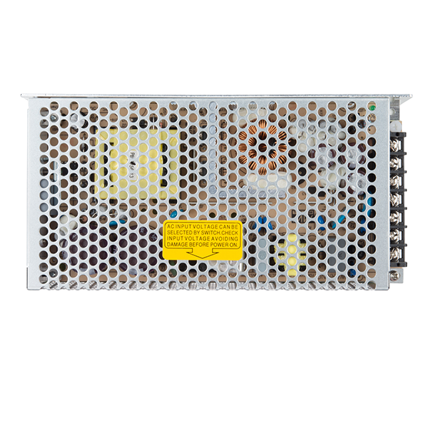
The Switching Power Supply (5V 30A), manufactured by Wanzheng Power (Part ID: WZ-0530J), is a high-efficiency device designed to convert electrical power from one voltage level to another. It provides a stable 5V DC output with a maximum current capacity of 30A, making it ideal for powering high-current devices and systems. This power supply is widely used in industrial automation, LED lighting systems, 3D printers, and other electronic applications requiring reliable and efficient power delivery.
Explore Projects Built with Switching Power Supply (5V 30A)


Explore Projects Built with Switching Power Supply (5V 30A)
Common Applications
- Powering LED strips and lighting systems
- Supplying power to 3D printers and CNC machines
- Industrial automation and control systems
- High-current microcontroller-based projects
- Battery charging systems
Technical Specifications
Below are the key technical details of the WZ-0530J switching power supply:
| Parameter | Value |
|---|---|
| Input Voltage Range | 110V AC or 220V AC (selectable) |
| Output Voltage | 5V DC |
| Maximum Output Current | 30A |
| Output Power | 150W |
| Efficiency | ≥85% |
| Ripple and Noise | ≤100mV |
| Operating Temperature | -10°C to +60°C |
| Cooling Method | Built-in fan (forced air cooling) |
| Dimensions | 215mm x 115mm x 50mm |
| Weight | ~800g |
| Safety Features | Overload, overvoltage, and short-circuit protection |
Pin Configuration and Descriptions
The WZ-0530J has screw terminal connections for input and output. Below is the pin configuration:
Input Terminals
| Pin Label | Description |
|---|---|
| L | Live AC input |
| N | Neutral AC input |
| GND | Earth/ground connection |
Output Terminals
| Pin Label | Description |
|---|---|
| V+ | Positive 5V DC output |
| V- | Negative (GND) output |
Additional Features
| Pin Label | Description |
|---|---|
| ADJ | Voltage adjustment (±10%) |
Usage Instructions
How to Use the Component in a Circuit
Input Voltage Selection:
- Before connecting the power supply, ensure the input voltage selector switch is set to the correct value (110V or 220V) based on your local AC mains supply.
- Failure to set the correct input voltage may damage the power supply.
Wiring the Input:
- Connect the L terminal to the live wire of the AC mains.
- Connect the N terminal to the neutral wire of the AC mains.
- Connect the GND terminal to the earth/ground wire for safety.
Wiring the Output:
- Connect the V+ terminal to the positive input of your load or circuit.
- Connect the V- terminal to the ground (negative) input of your load or circuit.
Voltage Adjustment:
- Use the ADJ screw to fine-tune the output voltage within ±10% of 5V if required.
Power On:
- After verifying all connections, power on the supply. The built-in fan will activate to ensure proper cooling.
Important Considerations and Best Practices
- Load Requirements: Ensure the total current draw of connected devices does not exceed 30A.
- Ventilation: Install the power supply in a well-ventilated area to prevent overheating.
- Safety: Always disconnect the power supply from the mains before making any wiring changes.
- Fuse Protection: Use an appropriate fuse on the input side to protect against overcurrent conditions.
- Voltage Adjustment: Avoid excessive adjustment of the output voltage to prevent damage to connected devices.
Example: Connecting to an Arduino UNO
The WZ-0530J can be used to power an Arduino UNO and other peripherals. Below is an example of how to connect it:
- Connect the V+ terminal to the Arduino's VIN pin.
- Connect the V- terminal to the Arduino's GND pin.
- Ensure the output voltage is set to 5V before powering the Arduino.
Sample Arduino Code
// Example code to blink an LED connected to pin 13
// Ensure the Arduino is powered by the WZ-0530J power supply

void setup() {
  pinMode(13, OUTPUT); // Set pin 13 as an output
}

void loop() {
  digitalWrite(13, HIGH); // Turn the LED on
  delay(1000);            // Wait for 1 second
  digitalWrite(13, LOW);  // Turn the LED off
  delay(1000);            // Wait for 1 second
}
Troubleshooting and FAQs
Common Issues and Solutions
No Output Voltage:
- Cause: Incorrect input voltage selection or loose connections.
- Solution: Verify the input voltage selector switch is set correctly and check all connections.
Overheating:
- Cause: Poor ventilation or excessive load.
- Solution: Ensure proper airflow around the power supply and reduce the load if it exceeds 30A.
Output Voltage Fluctuations:
- Cause: High ripple due to poor grounding or excessive load.
- Solution: Check the grounding connection and ensure the load is within the rated capacity.
Fan Not Working:
- Cause: Faulty fan or blocked ventilation.
- Solution: Inspect the fan for obstructions or damage and replace if necessary.
FAQs
Q1: Can I use this power supply to charge a 5V battery?
A1: Yes, but ensure the battery charging circuit includes proper current regulation to prevent overcharging.
Q2: Is the power supply waterproof?
A2: No, the WZ-0530J is not waterproof. Use it in a dry environment.
Q3: Can I adjust the output voltage beyond 5V?
A3: The output voltage can be adjusted within ±10% of 5V (4.5V to 5.5V). Exceeding this range may damage the power supply or connected devices.
Q4: What happens if the load exceeds 30A?
A4: The power supply's overload protection will activate, shutting down the output to prevent damage.
By following this documentation, users can safely and effectively utilize the WZ-0530J Switching Power Supply in their projects.