
How to Use 2 channel relay 5v: Examples, Pinouts, and Specs
 Design with 2 channel relay 5v in Cirkit Designer
Introduction
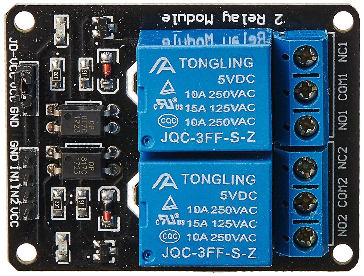
The 2 Channel Relay 5V module is an electronic component designed to control two independent circuits using low voltage signals. It operates at 5 volts and is widely used in automation projects, enabling the control of high voltage devices such as lights, fans, and appliances. This module acts as an interface between low-power microcontrollers (e.g., Arduino, Raspberry Pi) and high-power devices, ensuring safe and efficient switching.
Explore Projects Built with 2 channel relay 5v
 Open Project in Cirkit Designer
 Open Project in Cirkit Designer
 Open Project in Cirkit Designer
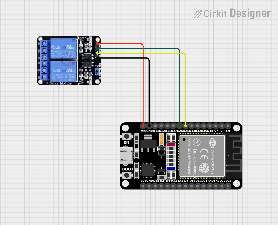 Open Project in Cirkit Designer
Explore Projects Built with 2 channel relay 5v
Open Project in Cirkit DesignerOpen Project in Cirkit DesignerOpen Project in Cirkit DesignerOpen Project in Cirkit DesignerCommon Applications
- Home automation systems
- Industrial control systems
- IoT projects
- Robotics
- Smart lighting and appliance control
Technical Specifications
The following table outlines the key technical details of the 2 Channel Relay 5V module:
| Parameter | Specification |
|---|---|
| Operating Voltage | 5V DC |
| Trigger Voltage | 3.3V to 5V DC |
| Relay Channels | 2 |
| Maximum Load (AC) | 250V AC @ 10A |
| Maximum Load (DC) | 30V DC @ 10A |
| Isolation | Optocoupler isolation |
| Dimensions | ~50mm x 40mm x 18mm |
| Indicator LEDs | Yes (one per channel) |
| Control Signal Logic | Active Low |
Pin Configuration
The 2 Channel Relay 5V module has the following pin layout:
Input Pins
| Pin Name | Description |
|---|---|
| VCC | Power supply input (5V DC) |
| GND | Ground connection |
| IN1 | Control signal for Relay 1 (Active Low) |
| IN2 | Control signal for Relay 2 (Active Low) |
Output Terminals (for each relay)
| Terminal Name | Description |
|---|---|
| COM | Common terminal for the relay |
| NO | Normally Open terminal (disconnected by default) |
| NC | Normally Closed terminal (connected by default) |
Usage Instructions
Connecting the Relay Module
- Power Supply: Connect the VCC pin to a 5V DC power source and the GND pin to ground.
- Control Signals: Connect the IN1 and IN2 pins to the digital output pins of a microcontroller (e.g., Arduino).
- Load Connections:
- For each relay, connect the device you want to control to the COM and NO/NC terminals.
- Use the NO terminal if you want the device to be off by default and turn on when the relay is activated.
- Use the NC terminal if you want the device to be on by default and turn off when the relay is activated.
Example Circuit with Arduino UNO
Below is an example of how to connect and control the 2 Channel Relay 5V module using an Arduino UNO:
Circuit Connections
- Connect the relay module's VCC to the Arduino's 5V pin.
- Connect the relay module's GND to the Arduino's GND pin.
- Connect IN1 to Arduino digital pin 7.
- Connect IN2 to Arduino digital pin 8.
- Connect the load (e.g., a light bulb) to the relay's COM and NO terminals.
Arduino Code Example
// Example code to control a 2 Channel Relay 5V module with Arduino UNO

// Define the relay control pins
const int relay1 = 7; // Relay 1 connected to digital pin 7
const int relay2 = 8; // Relay 2 connected to digital pin 8

void setup() {
  // Set relay pins as outputs
  pinMode(relay1, OUTPUT);
  pinMode(relay2, OUTPUT);

  // Initialize relays to OFF state (HIGH for active-low logic)
  digitalWrite(relay1, HIGH);
  digitalWrite(relay2, HIGH);
}

void loop() {
  // Turn on Relay 1
  digitalWrite(relay1, LOW); // Active-low logic: LOW turns the relay ON
  delay(1000); // Wait for 1 second

  // Turn off Relay 1
  digitalWrite(relay1, HIGH); // HIGH turns the relay OFF
  delay(1000); // Wait for 1 second

  // Turn on Relay 2
  digitalWrite(relay2, LOW); // Active-low logic: LOW turns the relay ON
  delay(1000); // Wait for 1 second

  // Turn off Relay 2
  digitalWrite(relay2, HIGH); // HIGH turns the relay OFF
  delay(1000); // Wait for 1 second
}
Best Practices
- Always use a separate power supply for the relay module if the load requires high current.
- Ensure proper insulation and safety precautions when working with high voltage devices.
- Use flyback diodes across inductive loads (e.g., motors) to protect the relay from voltage spikes.
Troubleshooting and FAQs
Common Issues
Relay Not Switching:
- Ensure the VCC and GND connections are secure.
- Verify that the control signal voltage is within the specified range (3.3V to 5V).
- Check if the relay module's indicator LEDs light up when activated.
Load Not Responding:
- Confirm that the load is properly connected to the COM and NO/NC terminals.
- Check the load's power supply and ensure it is functioning correctly.
Arduino Resets When Relay Activates:
- This may occur due to insufficient power supply. Use a separate power source for the relay module.
FAQs
Q: Can I use this relay module with a 3.3V microcontroller?
A: Yes, the module supports control signals as low as 3.3V. However, ensure the VCC pin is still supplied with 5V.
Q: Is the relay module safe for high voltage applications?
A: Yes, the module is designed for high voltage loads (up to 250V AC or 30V DC). However, always follow proper safety guidelines when working with high voltage.
Q: Can I control both relays simultaneously?
A: Yes, you can activate both relays at the same time by sending LOW signals to both IN1 and IN2.
Q: What is the purpose of the optocoupler isolation?
A: The optocoupler provides electrical isolation between the control circuit (e.g., Arduino) and the high voltage load, protecting the microcontroller from potential damage.