How to Use 150W DC-DC Boost Converter 10-32V to 12-35V 6A: Examples, Pinouts, and Specs
Introduction
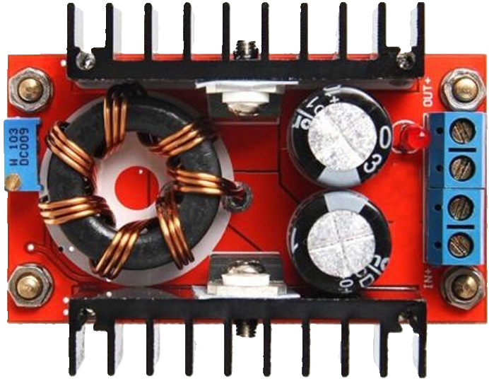
The 150W DC-DC Boost Converter is a power conversion device designed to step up a DC voltage from a lower input range (10-32V) to a higher output range (12-35V). It is capable of delivering a maximum output current of 6A, making it suitable for applications requiring increased voltage and power. This component is widely used in battery-powered systems, solar power setups, LED drivers, and other electronic projects where voltage boosting is necessary.
Explore Projects Built with 150W DC-DC Boost Converter 10-32V to 12-35V 6A


Explore Projects Built with 150W DC-DC Boost Converter 10-32V to 12-35V 6A
Common Applications
- Powering high-voltage devices from low-voltage batteries
- Solar panel voltage regulation
- LED lighting systems
- DIY electronics and robotics projects
- Automotive electronics
Technical Specifications
The following table outlines the key technical details of the 150W DC-DC Boost Converter:
| Parameter | Value |
|---|---|
| Input Voltage Range | 10V to 32V |
| Output Voltage Range | 12V to 35V (adjustable) |
| Maximum Output Current | 6A |
| Maximum Output Power | 150W |
| Efficiency | Up to 96% |
| Operating Temperature | -40°C to +85°C |
| Dimensions | 60mm x 52mm x 22mm |
| Weight | ~70g |
Pin Configuration and Descriptions
The module has four main connection points for input and output. The table below describes each pin:
| Pin Label | Description |
|---|---|
| VIN+ | Positive input voltage terminal (10-32V) |
| VIN- | Negative input voltage terminal (ground) |
| VOUT+ | Positive output voltage terminal (12-35V adjustable) |
| VOUT- | Negative output voltage terminal (ground) |
Usage Instructions
How to Use the Component in a Circuit
Connect the Input Voltage:
- Attach the positive terminal of your DC power source (e.g., battery or power supply) to the
VIN+pin. - Connect the negative terminal of the power source to the
VIN-pin.
- Attach the positive terminal of your DC power source (e.g., battery or power supply) to the
Connect the Output Load:
- Attach the positive terminal of your load (e.g., motor, LED, or other device) to the
VOUT+pin. - Connect the negative terminal of the load to the
VOUT-pin.
- Attach the positive terminal of your load (e.g., motor, LED, or other device) to the
Adjust the Output Voltage:
- Use the onboard potentiometer to adjust the output voltage. Turn the potentiometer clockwise to increase the voltage and counterclockwise to decrease it.
- Use a multimeter to measure the output voltage while adjusting to ensure accuracy.
Power On:
- Once all connections are secure, power on the input source. The module will boost the input voltage to the desired output level.
Important Considerations and Best Practices
- Ensure the input voltage is within the specified range (10-32V). Exceeding this range may damage the module.
- Do not exceed the maximum output current of 6A or the maximum power rating of 150W.
- Use a heatsink or active cooling if the module operates at high power for extended periods.
- Always measure the output voltage with a multimeter before connecting sensitive devices.
- Avoid short circuits between the input and output terminals.
Example: Using with an Arduino UNO
The 150W DC-DC Boost Converter can be used to power an Arduino UNO from a low-voltage battery. Below is an example setup:
- Connect a 12V battery to the
VIN+andVIN-terminals of the boost converter. - Adjust the output voltage to 9V using the potentiometer.
- Connect the
VOUT+andVOUT-terminals to the Arduino UNO's power input jack.
Here is a simple Arduino code example to blink an LED while powered by the boost converter:
// Simple LED Blink Example
// This code blinks an LED connected to pin 13 of the Arduino UNO.
// Ensure the boost converter is set to output 9V for safe operation.

void setup() {
  pinMode(13, OUTPUT); // Set pin 13 as an output
}

void loop() {
  digitalWrite(13, HIGH); // Turn the LED on
  delay(1000);            // Wait for 1 second
  digitalWrite(13, LOW);  // Turn the LED off
  delay(1000);            // Wait for 1 second
}
Troubleshooting and FAQs
Common Issues and Solutions
No Output Voltage:
- Check the input voltage to ensure it is within the 10-32V range.
- Verify all connections are secure and polarity is correct.
- Inspect the module for visible damage or overheating.
Output Voltage Not Adjustable:
- Ensure the potentiometer is not damaged or stuck.
- Use a multimeter to confirm the output voltage while adjusting.
Module Overheating:
- Reduce the load current or output power to stay within the 150W limit.
- Add a heatsink or active cooling to dissipate heat.
Load Not Powering On:
- Verify the output voltage matches the load's requirements.
- Check for loose or incorrect connections.
FAQs
Q: Can I use this module to charge a battery?
A: Yes, but ensure the output voltage is set to the appropriate charging voltage for the battery type. Use a current-limiting circuit if necessary.
Q: What happens if I exceed the input voltage range?
A: Exceeding the input voltage range (10-32V) can damage the module permanently. Always use a regulated power source.
Q: Can I use this module with a solar panel?
A: Yes, the module can boost the variable output of a solar panel to a stable voltage. Ensure the panel's voltage is within the input range.
Q: Is the output voltage stable under varying loads?
A: The module provides a stable output voltage under most conditions, but extreme load variations may cause minor fluctuations.