How to Use PLC: Examples, Pinouts, and Specs
Introduction
The Mitsubishi Electric Seku FX3U is a Programmable Logic Controller (PLC) designed for industrial automation applications. It is a compact, high-performance digital computer that automates electromechanical processes such as machinery control, assembly line operations, and lighting systems. The FX3U series is known for its flexibility, scalability, and ease of integration into various industrial environments.
Explore Projects Built with PLC


Explore Projects Built with PLC
Common Applications and Use Cases
- Factory automation and assembly line control
- Process monitoring and control in manufacturing
- Industrial robotics and motion control
- Building automation systems (e.g., HVAC, lighting)
- Amusement rides and entertainment systems
- Water treatment and utility management
Technical Specifications
The Mitsubishi Electric Seku FX3U PLC offers robust performance and a wide range of features to meet industrial automation needs.
Key Technical Details
| Specification | Value |
|---|---|
| Manufacturer | Mitsubishi Electric |
| Model | Seku FX3U |
| Power Supply Voltage | 24V DC or 100-240V AC (model-dependent) |
| Input Voltage Range | 24V DC (for digital inputs) |
| Output Voltage Range | 24V DC or 100-240V AC (model-dependent) |
| Number of I/O Points | Up to 384 (with expansion modules) |
| Communication Interfaces | RS-232, RS-485, Ethernet, USB |
| Programming Language | Ladder Logic, Structured Text, Function Block Diagram |
| Memory Capacity | 64k steps (expandable) |
| Operating Temperature Range | 0°C to 55°C |
| Dimensions | 90mm x 90mm x 75mm (base unit) |
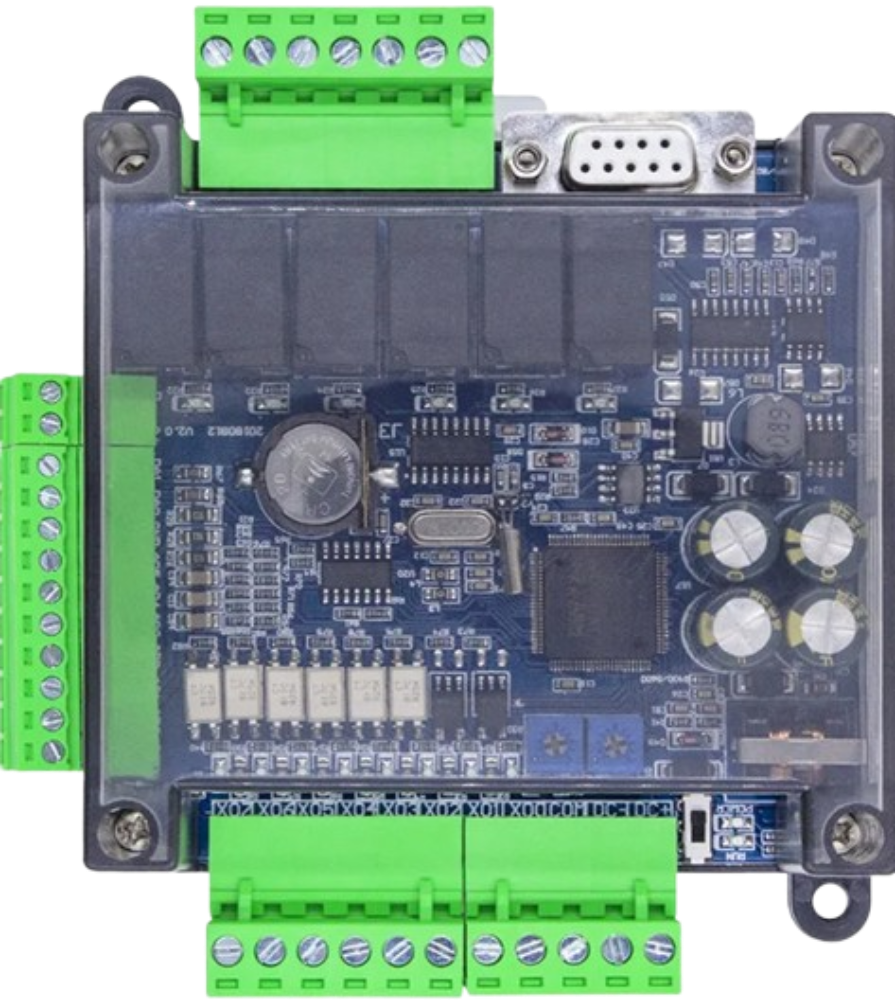
Pin Configuration and Descriptions
The FX3U PLC has multiple input and output terminals, which vary depending on the specific model and expansion modules. Below is an example of the base unit's pin configuration:
Digital Input Terminals
| Pin Number | Description | Voltage Level |
|---|---|---|
| X0 | Digital Input 0 | 24V DC |
| X1 | Digital Input 1 | 24V DC |
| X2 | Digital Input 2 | 24V DC |
| X3 | Digital Input 3 | 24V DC |
Digital Output Terminals
| Pin Number | Description | Voltage Level |
|---|---|---|
| Y0 | Digital Output 0 | 24V DC |
| Y1 | Digital Output 1 | 24V DC |
| Y2 | Digital Output 2 | 24V DC |
| Y3 | Digital Output 3 | 24V DC |
Power Terminals
| Pin Number | Description | Voltage Level |
|---|---|---|
| L/+ | Power Supply (Live/Positive) | 24V DC or AC |
| N/- | Power Supply (Neutral/Negative) | Ground |
Usage Instructions
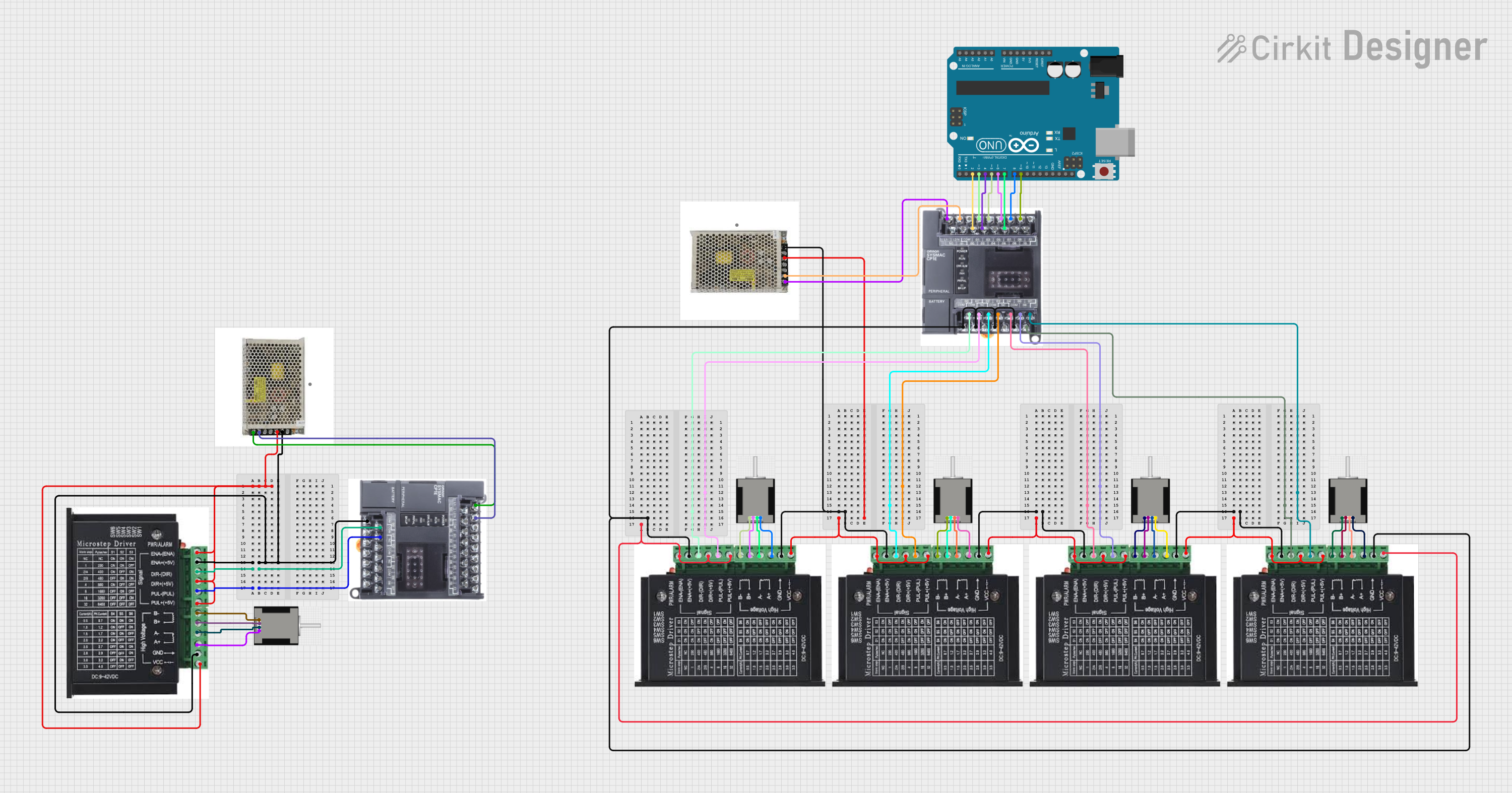
How to Use the FX3U PLC in a Circuit
- Power Connection: Connect the power supply to the L/+ and N/- terminals. Ensure the voltage matches the PLC's specifications (24V DC or 100-240V AC).
- Input Connections: Connect sensors, switches, or other input devices to the digital input terminals (e.g., X0, X1).
- Output Connections: Connect actuators, relays, or other output devices to the digital output terminals (e.g., Y0, Y1).
- Programming: Use Mitsubishi's GX Works2 or GX Developer software to write and upload your control program. The PLC supports Ladder Logic, Structured Text, and Function Block Diagram programming languages.
- Communication: Use the built-in communication interfaces (e.g., RS-232, Ethernet) to connect the PLC to other devices or a network.
Important Considerations and Best Practices
- Power Supply: Use a regulated power supply to avoid voltage fluctuations that could damage the PLC.
- Grounding: Properly ground the PLC to prevent electrical noise and ensure safe operation.
- Expansion Modules: If additional I/O points are needed, use compatible expansion modules from the FX3U series.
- Programming: Test your program in a simulation environment before deploying it to the PLC.
- Maintenance: Regularly inspect the PLC and its connections for signs of wear or damage.
Example Code for Arduino UNO Communication
The FX3U PLC can communicate with an Arduino UNO via RS-232 or RS-485. Below is an example of Arduino code to send data to the PLC:
#include <SoftwareSerial.h>

// Define RX and TX pins for SoftwareSerial
SoftwareSerial plcSerial(10, 11); // RX = pin 10, TX = pin 11

void setup() {
  // Initialize serial communication with the PLC
  plcSerial.begin(9600); // Set baud rate to match the PLC
  Serial.begin(9600);    // For debugging on the Serial Monitor

  // Send an initial message to the PLC
  plcSerial.println("Hello, PLC!"); // Replace with your PLC command
  Serial.println("Message sent to PLC.");
}

void loop() {
  // Check if the PLC has sent any data
  if (plcSerial.available()) {
    String plcResponse = plcSerial.readString();
    Serial.println("PLC Response: " + plcResponse);
  }

  // Add a delay to avoid flooding the communication
  delay(1000);
}
Note: Ensure the baud rate and communication settings (e.g., parity, stop bits) match the PLC's configuration.
Troubleshooting and FAQs
Common Issues and Solutions
PLC Not Powering On
- Cause: Incorrect power supply voltage or loose connections.
- Solution: Verify the power supply voltage and ensure all connections are secure.
Inputs Not Responding
- Cause: Faulty sensors or incorrect wiring.
- Solution: Check the input devices and wiring for faults or loose connections.
Outputs Not Activating
- Cause: Overloaded output terminals or incorrect programming.
- Solution: Verify the output load and review the control program for errors.
Communication Failure
- Cause: Mismatched baud rate or incorrect wiring.
- Solution: Ensure the communication settings match and check the wiring.
FAQs
Q: Can the FX3U PLC be used in harsh environments?
A: Yes, the FX3U is designed to operate in industrial environments with temperatures ranging from 0°C to 55°C. However, it should be protected from excessive dust, moisture, and vibration.
Q: How do I expand the I/O capacity of the FX3U?
A: Use compatible expansion modules from the FX3U series to increase the number of input and output points.
Q: What software is required to program the FX3U?
A: Mitsubishi's GX Works2 or GX Developer software is recommended for programming the FX3U PLC.
Q: Can the FX3U communicate with other PLCs or devices?
A: Yes, the FX3U supports multiple communication protocols, including RS-232, RS-485, and Ethernet, for integration with other devices.