Cirkit Designer
Your all-in-one circuit design IDE
Home /
Component Documentation
How to Use ws2812 led matrix 32x8: Examples, Pinouts, and Specs
Introduction
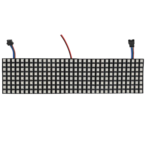
The WS2812 LED Matrix 32x8 is a versatile and vibrant display module consisting of 256 individually addressable RGB LEDs arranged in a 32x8 grid. Each LED can be controlled independently to display a wide range of colors, making this matrix ideal for creating dynamic and colorful displays, animations, and visual effects. The matrix is controlled via a single data line, simplifying the wiring and control process.
Explore Projects Built with ws2812 led matrix 32x8
ESP32-Controlled WS2812 LED Matrix Display with Resistor

This circuit features an ESP32 microcontroller connected to a 32x8 WS2812 LED matrix. The ESP32 controls the LED matrix through a 220-ohm resistor connected to its D12 pin, providing data input to the matrix, while power and ground connections are shared between the ESP32 and the LED matrix.
ESP32-Controlled Dual 8x8 LED Matrix Display with NTP Time Synchronization

This circuit features an ESP32 microcontroller connected to two cascaded 8x8 LED matrix displays, powered by a 3.3V battery. The ESP32 drives the displays to show time and other information, with the code indicating functionality for connecting to WiFi, synchronizing time via NTP, and displaying data on the matrices using custom fonts. Additionally, there is a separate 3.3V battery powering a red LED, which appears to function as a simple indicator light.
ESP32-Based Smart Weather Station with LED Display and Multiple Sensors

This circuit is a sensor and display system powered by an ESP32 microcontroller. It integrates multiple sensors (BH1750 light sensor, BMP280 pressure sensor, DS3231 RTC, and DS18B20 temperature sensor) and drives a series of MAX7219 8x8 LED matrices for visual output. The ESP32 communicates with the sensors via I2C and controls the LED matrices to display data.
ESP8266 NodeMCU Controlled 8x8 LED Matrix Display
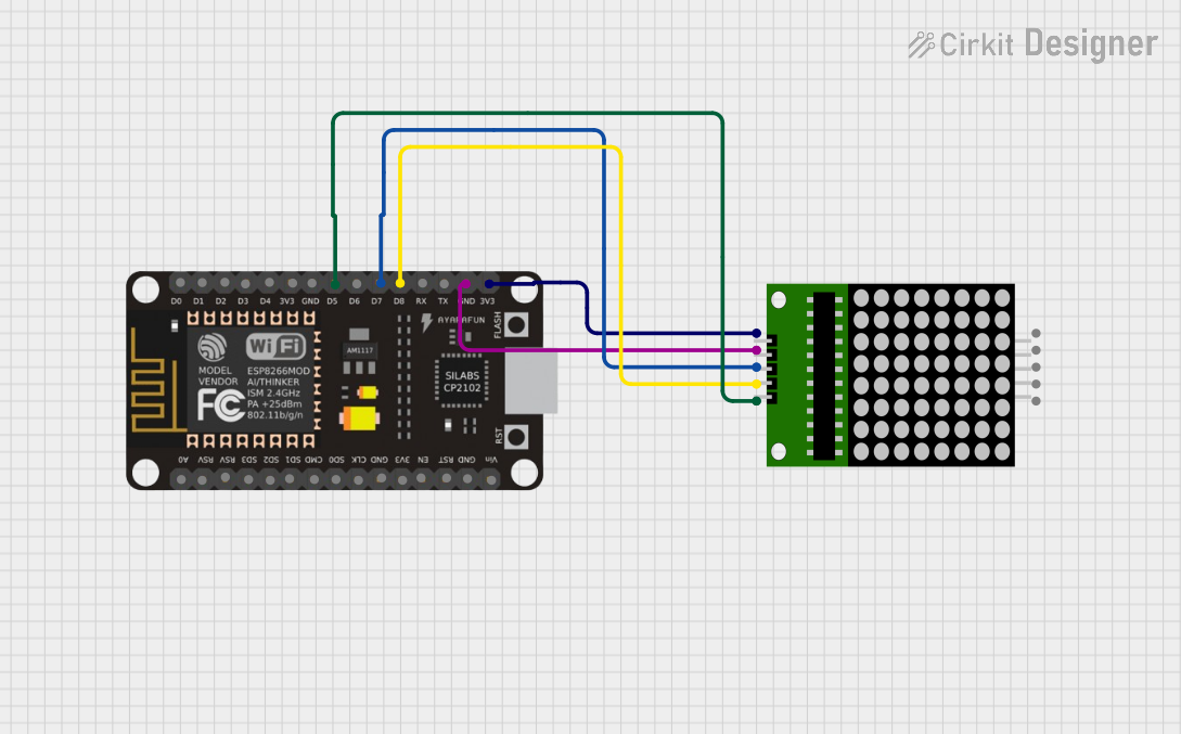
This circuit connects an ESP8266 NodeMCU microcontroller to an 8x8 LED matrix display. The NodeMCU controls the matrix using digital pins D5, D7, and D8 for chip select (CS), data input (DIN), and clock (CLK) signals, respectively. The circuit is designed to display patterns or characters on the LED matrix, which are driven by the microcontroller.
Explore Projects Built with ws2812 led matrix 32x8
ESP32-Controlled WS2812 LED Matrix Display with Resistor
This circuit features an ESP32 microcontroller connected to a 32x8 WS2812 LED matrix. The ESP32 controls the LED matrix through a 220-ohm resistor connected to its D12 pin, providing data input to the matrix, while power and ground connections are shared between the ESP32 and the LED matrix.
ESP32-Controlled Dual 8x8 LED Matrix Display with NTP Time Synchronization
This circuit features an ESP32 microcontroller connected to two cascaded 8x8 LED matrix displays, powered by a 3.3V battery. The ESP32 drives the displays to show time and other information, with the code indicating functionality for connecting to WiFi, synchronizing time via NTP, and displaying data on the matrices using custom fonts. Additionally, there is a separate 3.3V battery powering a red LED, which appears to function as a simple indicator light.
ESP32-Based Smart Weather Station with LED Display and Multiple Sensors
This circuit is a sensor and display system powered by an ESP32 microcontroller. It integrates multiple sensors (BH1750 light sensor, BMP280 pressure sensor, DS3231 RTC, and DS18B20 temperature sensor) and drives a series of MAX7219 8x8 LED matrices for visual output. The ESP32 communicates with the sensors via I2C and controls the LED matrices to display data.
ESP8266 NodeMCU Controlled 8x8 LED Matrix Display
This circuit connects an ESP8266 NodeMCU microcontroller to an 8x8 LED matrix display. The NodeMCU controls the matrix using digital pins D5, D7, and D8 for chip select (CS), data input (DIN), and clock (CLK) signals, respectively. The circuit is designed to display patterns or characters on the LED matrix, which are driven by the microcontroller.
Common Applications and Use Cases
- Digital Signage: Display text, images, and animations for advertising or information.
- Wearable Technology: Integrate into clothing or accessories for eye-catching designs.
- Art Installations: Create interactive and dynamic art pieces.
- Home Automation: Use as a status display for smart home systems.
- Gaming: Enhance gaming setups with custom lighting effects.
Technical Specifications
Key Technical Details
| Parameter | Value |
|---|---|
| LED Type | WS2812B |
| LED Count | 256 (32x8) |
| Voltage | 5V DC |
| Current (max) | ~15A (at full brightness) |
| Power Consumption | ~75W (at full brightness) |
| Communication | Single-wire (data line) |
| Color Depth | 24-bit (8 bits per color) |
| Dimensions | 320mm x 80mm |
Pin Configuration and Descriptions
| Pin Name | Description |
|---|---|
| VCC | Power supply (5V) |
| GND | Ground |
| DIN | Data input |
| DOUT | Data output (for chaining) |
Usage Instructions
How to Use the Component in a Circuit
- Power Supply: Connect the VCC pin to a 5V power supply and the GND pin to the ground.
- Data Line: Connect the DIN pin to a digital output pin on your microcontroller (e.g., Arduino).
- Chaining Matrices: If you need to chain multiple matrices, connect the DOUT pin of the first matrix to the DIN pin of the next matrix.
Important Considerations and Best Practices
- Power Supply: Ensure your power supply can provide sufficient current. At full brightness, the matrix can draw up to 15A.
- Capacitor: Place a 1000µF capacitor across the VCC and GND pins to smooth out power supply fluctuations.
- Resistor: Use a 330Ω resistor between the microcontroller's data pin and the DIN pin to protect the LEDs from voltage spikes.
- Heat Management: The matrix can get warm during operation. Ensure adequate ventilation or heat dissipation.
Example Code for Arduino UNO
#include <Adafruit_NeoPixel.h>

// Define the pin connected to the DIN of the matrix
#define DATA_PIN 6

// Define the number of LEDs in the matrix
#define NUM_LEDS 256

// Create an instance of the Adafruit_NeoPixel class
Adafruit_NeoPixel strip = Adafruit_NeoPixel(NUM_LEDS, DATA_PIN, NEO_GRB + NEO_KHZ800);

void setup() {
  strip.begin(); // Initialize the strip
  strip.show();  // Initialize all pixels to 'off'
}

void loop() {
  // Example: Fill the matrix with red color
  for (int i = 0; i < NUM_LEDS; i++) {
    strip.setPixelColor(i, strip.Color(255, 0, 0)); // Set pixel to red
  }
  strip.show(); // Update the strip to show the color
  delay(1000);  // Wait for 1 second

  // Example: Turn off all LEDs
  for (int i = 0; i < NUM_LEDS; i++) {
    strip.setPixelColor(i, strip.Color(0, 0, 0)); // Turn off pixel
  }
  strip.show(); // Update the strip to turn off LEDs
  delay(1000);  // Wait for 1 second
}
Troubleshooting and FAQs
Common Issues Users Might Face
LEDs Not Lighting Up:
- Solution: Check the power supply connections and ensure the voltage is 5V. Verify the data line connection and ensure the microcontroller is properly programmed.
Flickering or Incorrect Colors:
- Solution: Ensure a 330Ω resistor is used on the data line. Check for loose connections and ensure the power supply can handle the current draw.
Matrix Overheating:
- Solution: Reduce the brightness of the LEDs or improve ventilation around the matrix.
Solutions and Tips for Troubleshooting
- Check Connections: Ensure all connections are secure and correct.
- Use a Stable Power Supply: A stable 5V power supply is crucial for proper operation.
- Test with Simple Code: Start with simple code to test the matrix before moving on to complex animations.
- Consult the Datasheet: Refer to the WS2812B datasheet for detailed technical information.
By following this documentation, users can effectively utilize the WS2812 LED Matrix 32x8 in their projects, creating stunning visual displays and animations.