How to Use Module Lora E01-ML01DP5: Examples, Pinouts, and Specs
Introduction
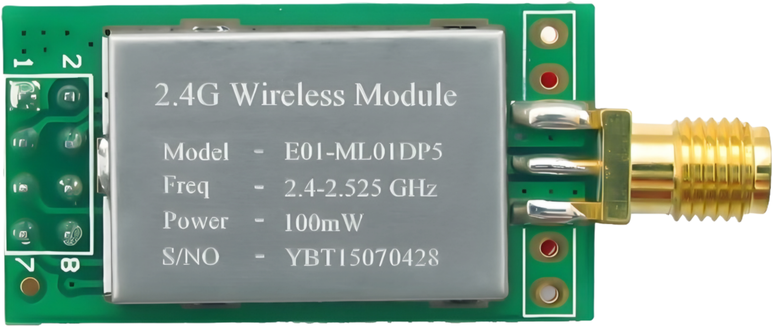
The E01-ML01DP5 is a low-power, long-range wireless communication module based on LoRa (Long Range) technology. It is designed for Internet of Things (IoT) applications, offering reliable data transmission over extended distances. Operating in the 433MHz, 868MHz, or 915MHz frequency bands, this module is ideal for remote sensor networks, industrial automation, smart agriculture, and other applications requiring robust, low-power communication.
Explore Projects Built with Module Lora E01-ML01DP5
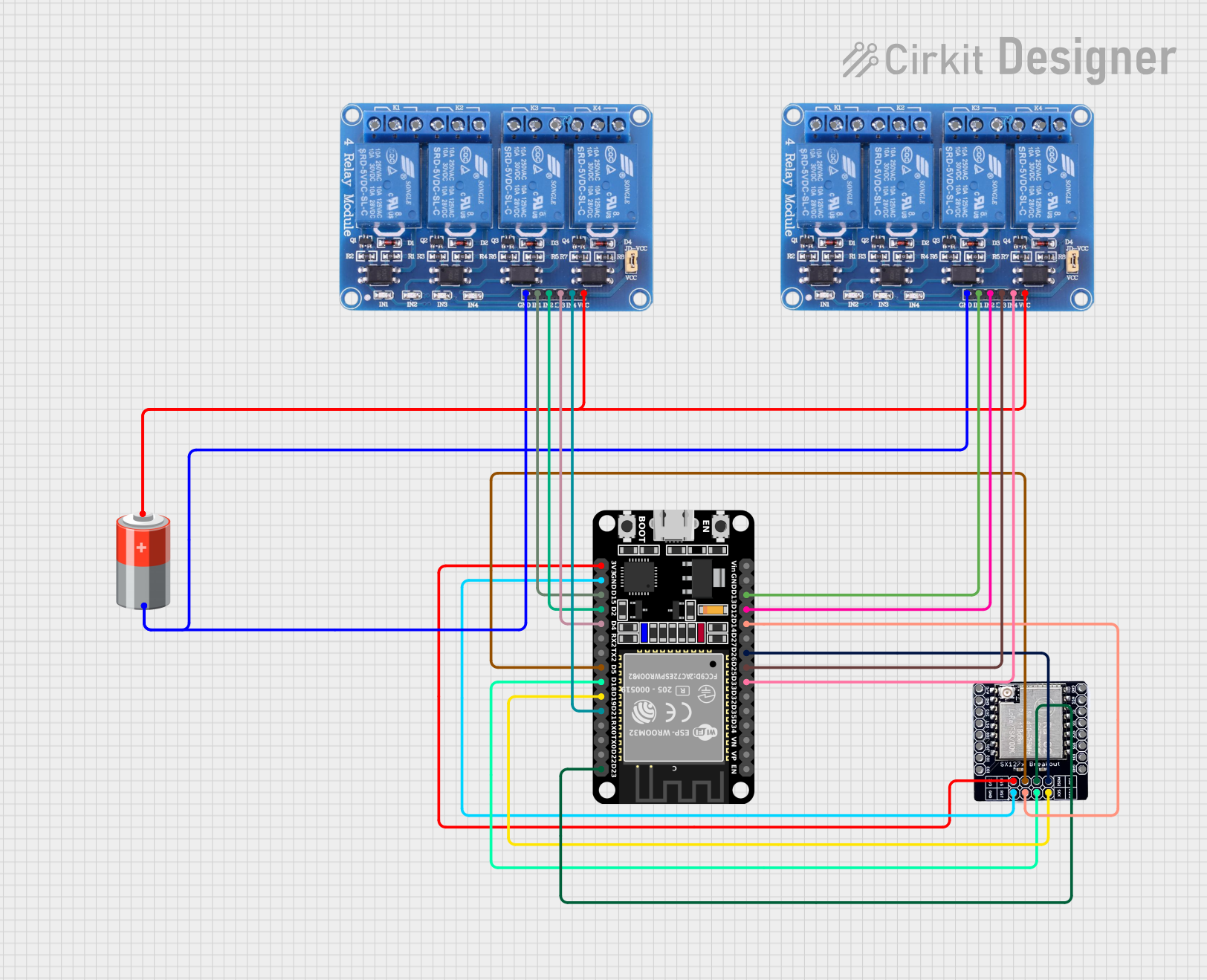

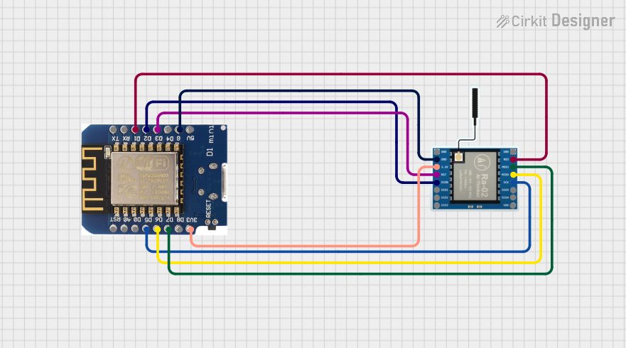

Explore Projects Built with Module Lora E01-ML01DP5
Common Applications and Use Cases
- Remote sensor networks for environmental monitoring
- Smart agriculture (e.g., soil moisture and weather monitoring)
- Industrial automation and control systems
- Smart cities (e.g., parking systems, street lighting)
- Asset tracking and logistics
- Home automation and security systems
Technical Specifications
The E01-ML01DP5 module is designed to provide high performance while maintaining low power consumption. Below are its key technical specifications:
| Parameter | Value |
|---|---|
| Frequency Band | 433MHz / 868MHz / 915MHz |
| Modulation Technique | LoRa |
| Transmission Power | Up to 30dBm (1W) |
| Sensitivity | -139dBm |
| Communication Distance | Up to 5km (line of sight) |
| Operating Voltage | 2.3V to 5.5V |
| Current Consumption | 100mA (transmit), 15mA (receive) |
| Interface | UART (TTL level) |
| Data Rate | 0.3kbps to 19.2kbps |
| Operating Temperature | -40°C to +85°C |
| Dimensions | 24mm x 43mm x 3mm |
Pin Configuration and Descriptions
The E01-ML01DP5 module has a total of 8 pins. Below is the pinout and description:
| Pin Number | Pin Name | Description |
|---|---|---|
| 1 | VCC | Power supply input (2.3V to 5.5V) |
| 2 | GND | Ground |
| 3 | TXD | UART Transmit (data output) |
| 4 | RXD | UART Receive (data input) |
| 5 | AUX | Status indicator pin (low during transmission) |
| 6 | M0 | Mode selection pin 0 |
| 7 | M1 | Mode selection pin 1 |
| 8 | ANT | Antenna interface (50Ω impedance) |
Usage Instructions
How to Use the E01-ML01DP5 in a Circuit
- Power Supply: Connect the VCC pin to a stable power source (2.3V to 5.5V) and the GND pin to ground.
- UART Communication: Connect the TXD and RXD pins to the UART pins of your microcontroller (e.g., Arduino UNO). Use a logic level converter if your microcontroller operates at 3.3V or 5V.
- Mode Selection: Use the M0 and M1 pins to configure the module's operating mode:
- Mode 0 (Normal): M0 = 0, M1 = 0
- Mode 1 (Wake-up): M0 = 1, M1 = 0
- Mode 2 (Power-saving): M0 = 0, M1 = 1
- Mode 3 (Configuration): M0 = 1, M1 = 1
- Antenna: Connect a suitable 433MHz, 868MHz, or 915MHz antenna to the ANT pin for optimal performance.
Important Considerations and Best Practices
- Ensure the antenna is properly matched to the operating frequency for maximum range and efficiency.
- Avoid placing the module near high-frequency noise sources or metal enclosures that may interfere with signal transmission.
- Use decoupling capacitors near the VCC pin to stabilize the power supply.
- Configure the module's parameters (e.g., frequency, data rate) using AT commands in Configuration Mode (Mode 3).
Example: Connecting to an Arduino UNO
Below is an example of how to connect the E01-ML01DP5 to an Arduino UNO and send data:
Wiring Diagram
| E01-ML01DP5 Pin | Arduino UNO Pin |
|---|---|
| VCC | 5V |
| GND | GND |
| TXD | Pin 2 (RX) |
| RXD | Pin 3 (TX) |
| M0 | GND |
| M1 | GND |
| AUX | Not connected |
| ANT | Antenna |
Arduino Code
#include <SoftwareSerial.h>

// Define RX and TX pins for SoftwareSerial
SoftwareSerial loraSerial(2, 3); // RX = Pin 2, TX = Pin 3

void setup() {
  // Initialize serial communication
  Serial.begin(9600); // For debugging
  loraSerial.begin(9600); // For LoRa module communication

  Serial.println("E01-ML01DP5 LoRa Module Test");
}

void loop() {
  // Send data to the LoRa module
  loraSerial.println("Hello, LoRa!");
  Serial.println("Data sent: Hello, LoRa!");

  // Wait for 1 second before sending the next message
  delay(1000);
}
Troubleshooting and FAQs
Common Issues and Solutions
No Communication with the Module
- Cause: Incorrect UART connection or baud rate mismatch.
- Solution: Verify the TXD and RXD connections. Ensure the baud rate matches the module's default (9600bps).
Short Communication Range
- Cause: Poor antenna connection or interference.
- Solution: Check the antenna connection and ensure it matches the operating frequency. Avoid obstructions and interference sources.
Module Not Responding to AT Commands
- Cause: Incorrect mode configuration.
- Solution: Ensure the module is in Configuration Mode (M0 = 1, M1 = 1) before sending AT commands.
High Power Consumption
- Cause: Module operating in Normal Mode continuously.
- Solution: Use Power-saving Mode (M0 = 0, M1 = 1) when the module is idle.
FAQs
What is the maximum range of the E01-ML01DP5?
- The module can achieve up to 5km range in line-of-sight conditions with a proper antenna.
Can I use the module with a 3.3V microcontroller?
- Yes, the module supports a wide voltage range (2.3V to 5.5V). Ensure the UART logic levels are compatible.
How do I change the module's frequency?
- Use AT commands in Configuration Mode to set the desired frequency. Refer to the module's datasheet for detailed AT command instructions.
Is the module suitable for battery-powered applications?
- Yes, the module's low-power design makes it ideal for battery-powered IoT devices. Use Power-saving Mode to extend battery life.