
How to Use USB-C with OTG: Examples, Pinouts, and Specs
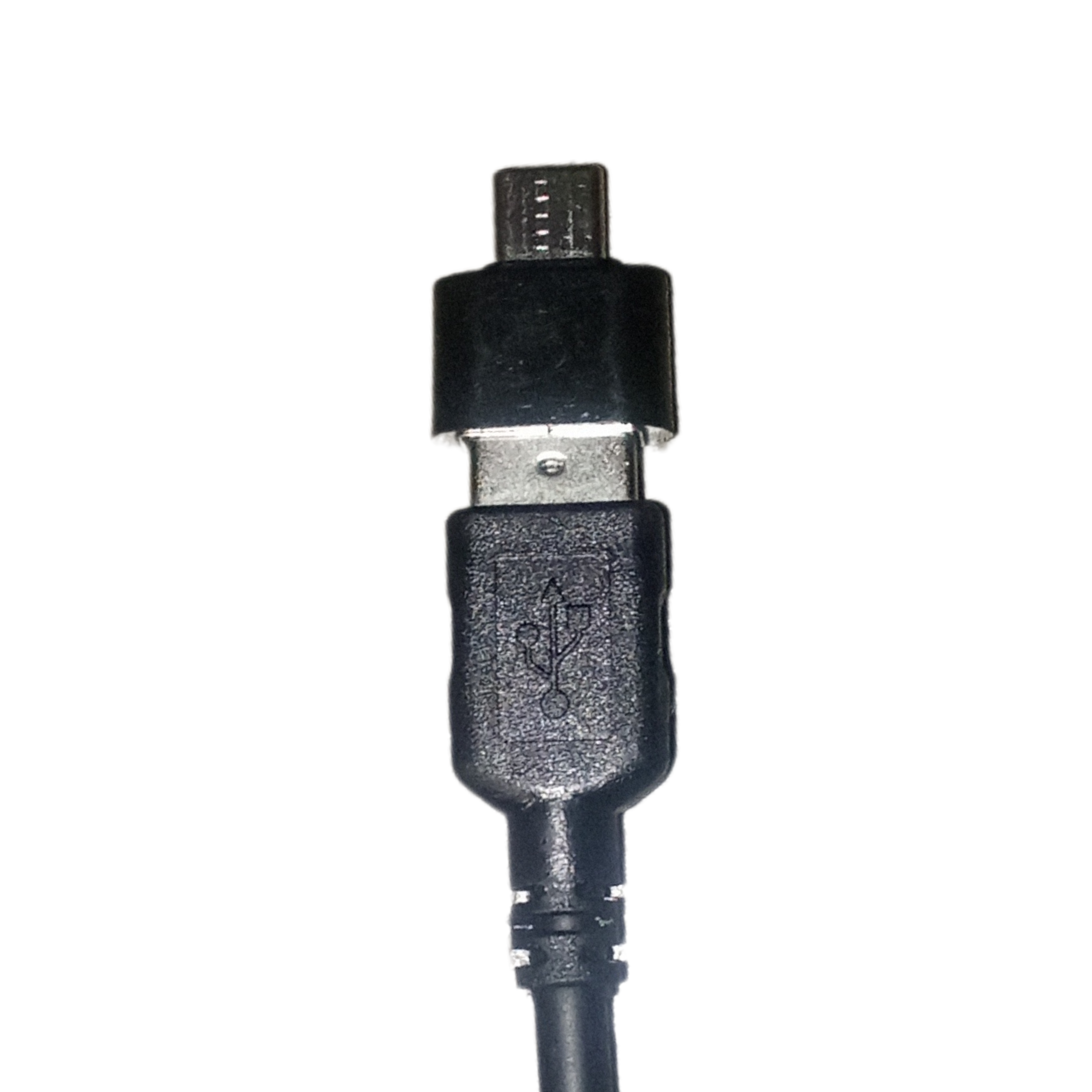
 Design with USB-C with OTG in Cirkit Designer
Introduction
The USB-C with OTG (On-The-Go) connector is a versatile and compact interface that supports both data transfer and power delivery. Its OTG functionality allows devices to act as a host, enabling them to connect to peripherals such as keyboards, mice, flash drives, and other USB-enabled devices. This makes it an essential component for modern electronics, particularly in portable devices like smartphones, tablets, and embedded systems.
Explore Projects Built with USB-C with OTG
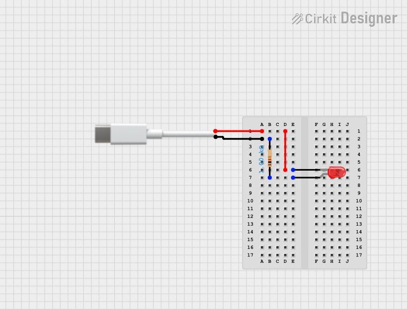 Open Project in Cirkit Designer
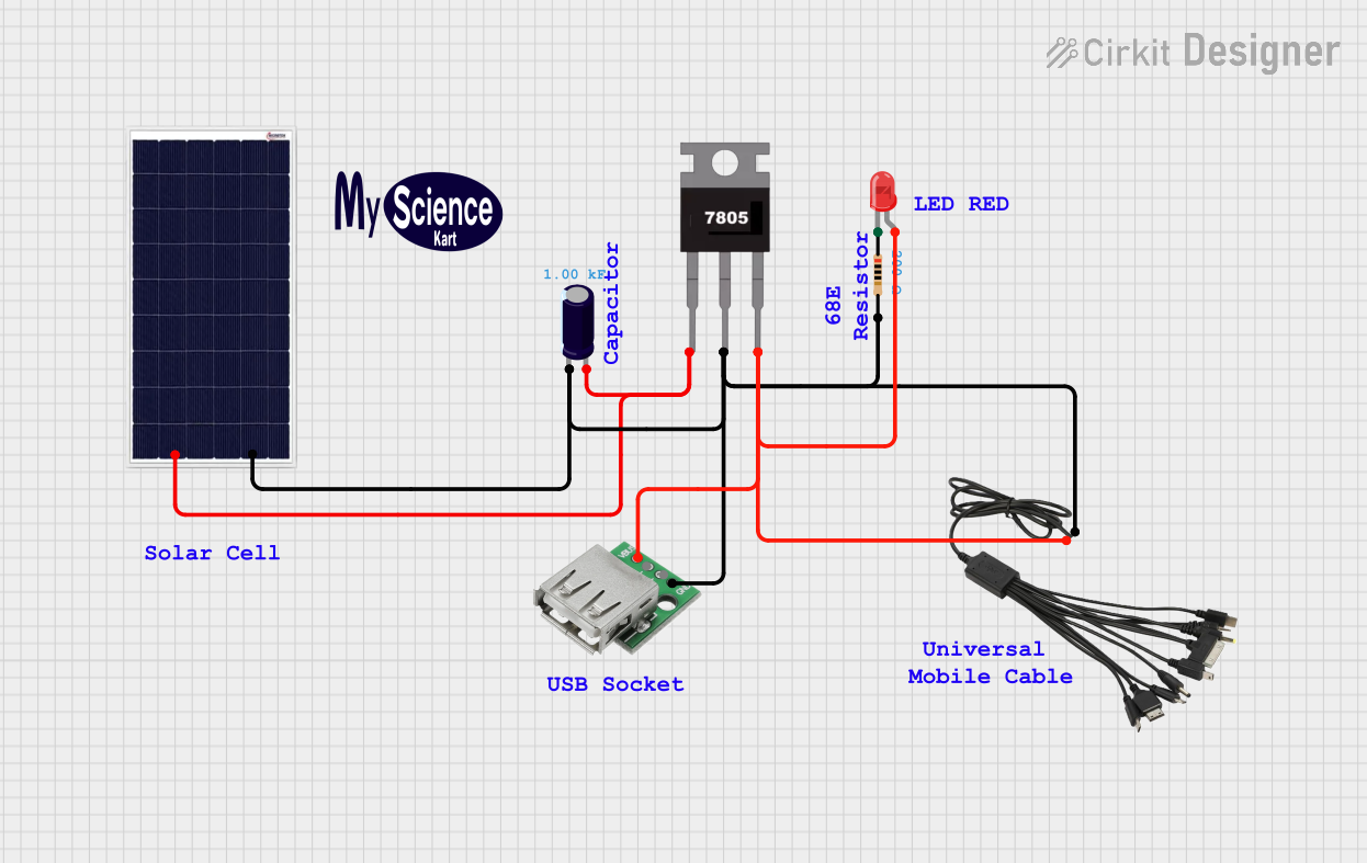 Open Project in Cirkit Designer
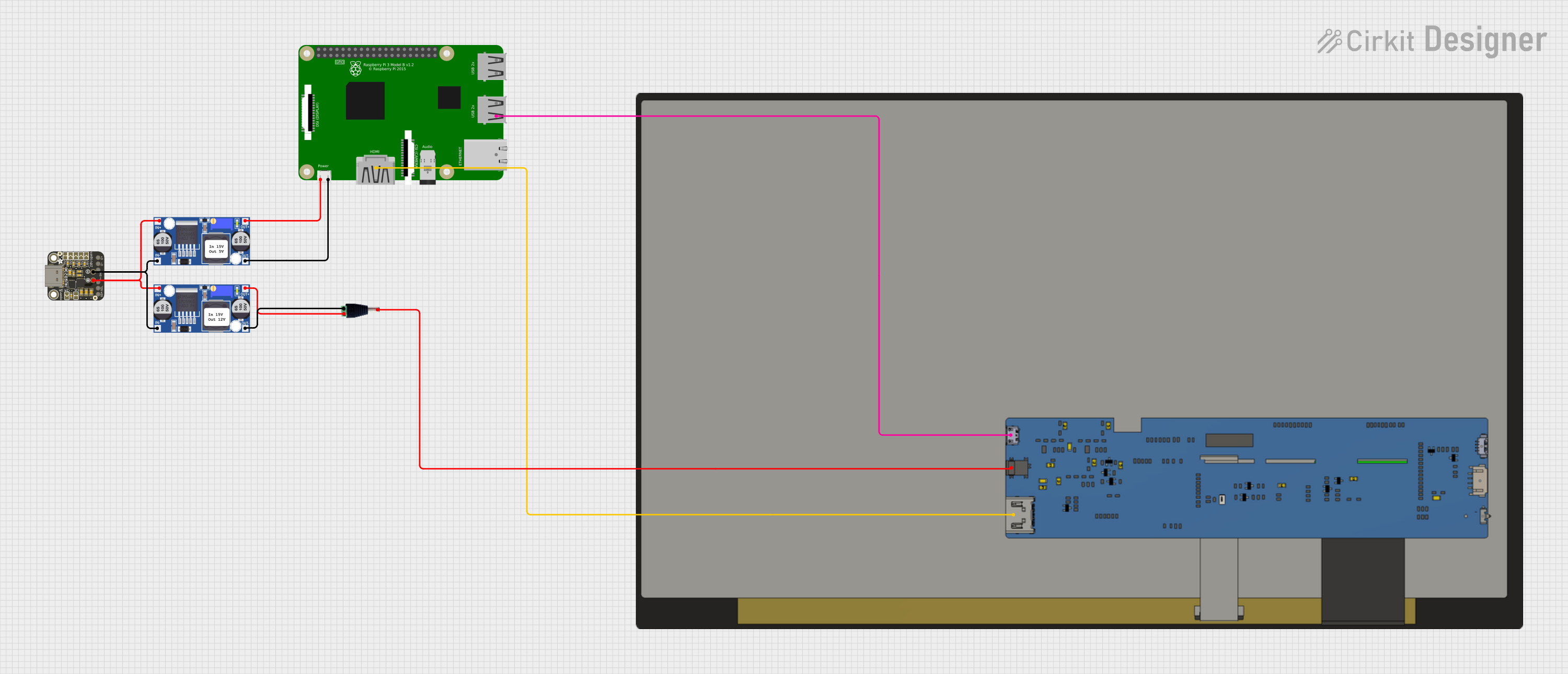 Open Project in Cirkit Designer
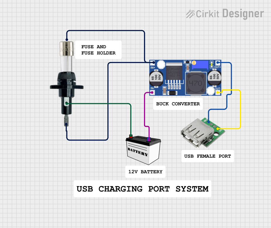 Open Project in Cirkit Designer
Explore Projects Built with USB-C with OTG
Open Project in Cirkit DesignerOpen Project in Cirkit DesignerOpen Project in Cirkit DesignerOpen Project in Cirkit DesignerCommon Applications and Use Cases
- Smartphones and tablets connecting to external storage or input devices
- Embedded systems requiring USB host functionality
- Portable devices with dual roles (host and peripheral)
- USB-C hubs and adapters for expanding connectivity
- DIY electronics projects involving USB peripherals
Technical Specifications
Key Technical Details
- Connector Type: USB Type-C
- OTG Support: Yes
- Voltage Rating: 5V (standard USB power), up to 20V for Power Delivery (PD)
- Current Rating: Up to 3A (standard), 5A with Power Delivery
- Data Transfer Rate: Up to 10Gbps (USB 3.1 Gen 2), backward compatible with USB 2.0
- Operating Temperature: -40°C to 85°C
- Durability: Rated for 10,000+ insertion/removal cycles
Pin Configuration and Descriptions
The USB-C connector has a symmetrical design with 24 pins. Below is a simplified pinout for OTG functionality:
| Pin Name | Pin Number | Description |
|---|---|---|
| GND | A1, A12, B1, B12 | Ground connection |
| VBUS | A4, B4 | Power supply (5V, up to 20V with PD) |
| D+ | A6, B6 | USB 2.0 differential data line (positive) |
| D- | A7, B7 | USB 2.0 differential data line (negative) |
| CC1 | A5 | Configuration channel for OTG and PD |
| CC2 | B5 | Configuration channel for OTG and PD |
| TX+ | A2, B10 | USB 3.x SuperSpeed differential pair |
| TX- | A3, B11 | USB 3.x SuperSpeed differential pair |
| RX+ | A10, B2 | USB 3.x SuperSpeed differential pair |
| RX- | A11, B3 | USB 3.x SuperSpeed differential pair |
| SBU1 | A8 | Sideband use (e.g., audio, debug) |
| SBU2 | B8 | Sideband use (e.g., audio, debug) |
Usage Instructions
How to Use the USB-C with OTG in a Circuit
- Power Supply: Ensure the VBUS pin is supplied with 5V (or higher if using Power Delivery). Use appropriate current-limiting circuitry to prevent overcurrent conditions.
- OTG Configuration: Use the CC1 and CC2 pins to configure the device as a host or peripheral. For OTG functionality, connect a pull-up or pull-down resistor to the CC pins as per the USB-C specification.
- Data Lines: Connect the D+ and D- pins for USB 2.0 communication. For USB 3.x, also connect the TX+/TX- and RX+/RX- differential pairs.
- Peripheral Connection: Attach the desired USB device (e.g., keyboard, mouse, or flash drive) to the USB-C port. Ensure the connected device is compatible with OTG functionality.
- Testing: Verify the connection by checking data transfer or peripheral functionality.
Important Considerations and Best Practices
- Use high-quality USB-C connectors and cables to ensure reliable performance.
- For Power Delivery, ensure the circuit includes a USB PD controller to negotiate voltage and current levels.
- Avoid exceeding the rated voltage and current to prevent damage to the connector or connected devices.
- When designing for OTG, ensure proper pull-up/pull-down resistor values on the CC pins to indicate the device's role (host or peripheral).
- Use ESD protection on data lines to safeguard against electrostatic discharge.
Example: Connecting USB-C with OTG to an Arduino UNO
While the Arduino UNO does not natively support USB-C, you can use a USB-C breakout board with OTG functionality to interface with peripherals. Below is an example of using an Arduino UNO to detect a USB device connected via OTG:
// Example code for detecting a USB device connected via OTG
// Note: Requires a USB host shield or similar hardware for Arduino UNO

#include <USBHost.h> // Include USB Host library

USBHost usb; // Create USBHost object

void setup() {
  Serial.begin(9600); // Initialize serial communication
  while (!Serial);    // Wait for serial monitor to open

  Serial.println("Initializing USB Host...");
  if (usb.begin()) {
    Serial.println("USB Host initialized successfully.");
  } else {
    Serial.println("Failed to initialize USB Host.");
  }
}

void loop() {
  usb.Task(); // Process USB tasks

  // Check if a device is connected
  if (usb.getDeviceCount() > 0) {
    Serial.println("USB device detected!");
  } else {
    Serial.println("No USB device connected.");
  }

  delay(1000); // Wait 1 second before checking again
}
Troubleshooting and FAQs
Common Issues and Solutions
Device Not Recognized:
- Cause: Incorrect pull-up/pull-down resistor configuration on CC pins.
- Solution: Verify resistor values and connections. Ensure the device is configured as a host or peripheral correctly.
No Power to Connected Device:
- Cause: Insufficient power supply or faulty VBUS connection.
- Solution: Check the VBUS pin voltage and current. Use a stable power source.
Data Transfer Fails:
- Cause: Poor-quality cable or incorrect data line connections.
- Solution: Use a certified USB-C cable and verify D+/D- or TX/RX connections.
Overheating:
- Cause: Excessive current draw or poor thermal management.
- Solution: Ensure current does not exceed the rated limit. Use heat sinks if necessary.
FAQs
Q1: Can I use USB-C with OTG for charging and data transfer simultaneously?
A1: Yes, USB-C supports simultaneous charging and data transfer. However, ensure proper circuit design to handle both functionalities.
Q2: What resistor values should I use for OTG configuration?
A2: Typically, a 5.1kΩ pull-down resistor is used on the CC pins for a host device, and a 56kΩ pull-up resistor is used for a peripheral device.
Q3: Is USB-C with OTG backward compatible with USB 2.0 devices?
A3: Yes, USB-C is backward compatible with USB 2.0. Ensure the D+/D- lines are connected for USB 2.0 communication.
Q4: Can I use USB-C with OTG for audio output?
A4: Yes, the SBU1 and SBU2 pins can be used for analog audio in some implementations. Check the device's specifications for compatibility.