How to Use Traffic light: Examples, Pinouts, and Specs
Introduction
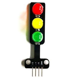
The Traffic Light is a signaling device designed to control traffic flow at intersections. It uses three colored lights—red, yellow, and green—to indicate stop, caution, and go, respectively. This component is commonly used in educational projects, prototyping, and IoT applications to simulate real-world traffic systems.
Manufactured by Arduino, the Traffic Light (Part ID: UNO) is ideal for integration with microcontrollers like the Arduino UNO, enabling users to create interactive and programmable traffic control systems.
Explore Projects Built with Traffic light
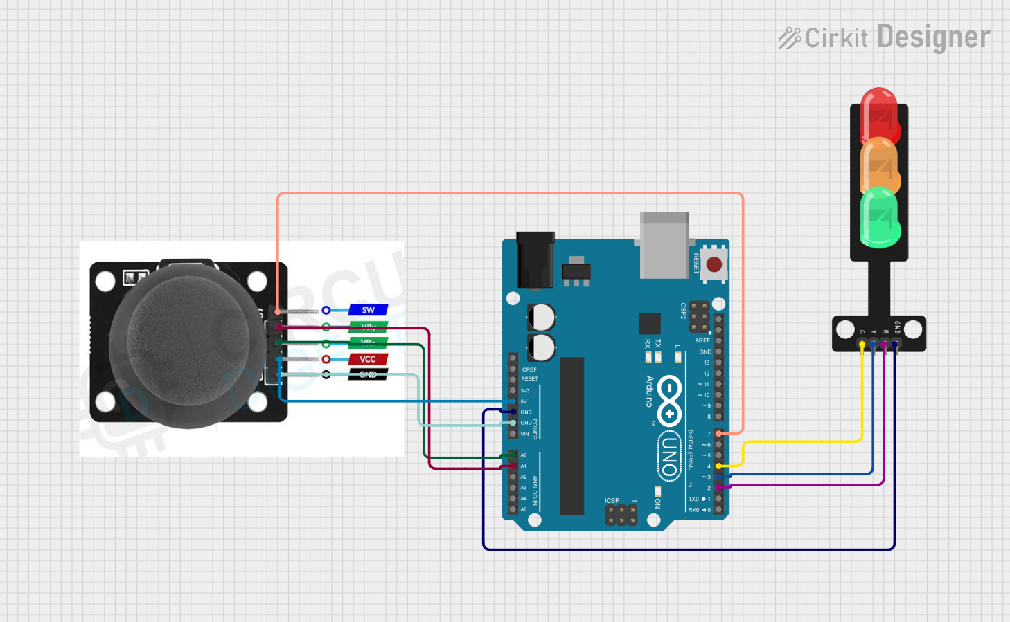
Explore Projects Built with Traffic light
Common Applications and Use Cases
- Traffic flow simulation in educational projects
- Smart city and IoT-based traffic management systems
- Prototyping for autonomous vehicle navigation
- Demonstrations of timing and sequencing in embedded systems
Technical Specifications
Key Technical Details
- Operating Voltage: 5V DC (compatible with Arduino UNO)
- Current Consumption: ~20mA per LED
- LED Colors: Red, Yellow, Green
- Control Method: Digital I/O pins
- Dimensions: Varies based on the module (typically ~50mm x 20mm)
Pin Configuration and Descriptions
The Traffic Light module typically has four pins for connection. Below is the pin configuration:
| Pin | Name | Description |
|---|---|---|
| 1 | Red LED | Connect to a digital output pin to control the red light. |
| 2 | Yellow LED | Connect to a digital output pin to control the yellow light. |
| 3 | Green LED | Connect to a digital output pin to control the green light. |
| 4 | Ground (GND) | Connect to the ground pin of the Arduino UNO or power supply. |
Usage Instructions
How to Use the Component in a Circuit
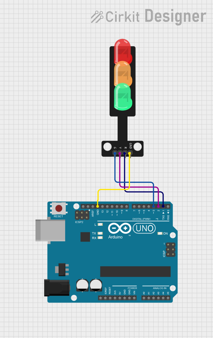
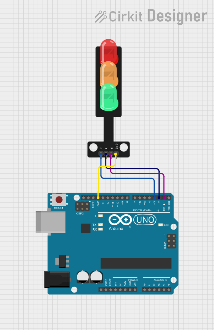
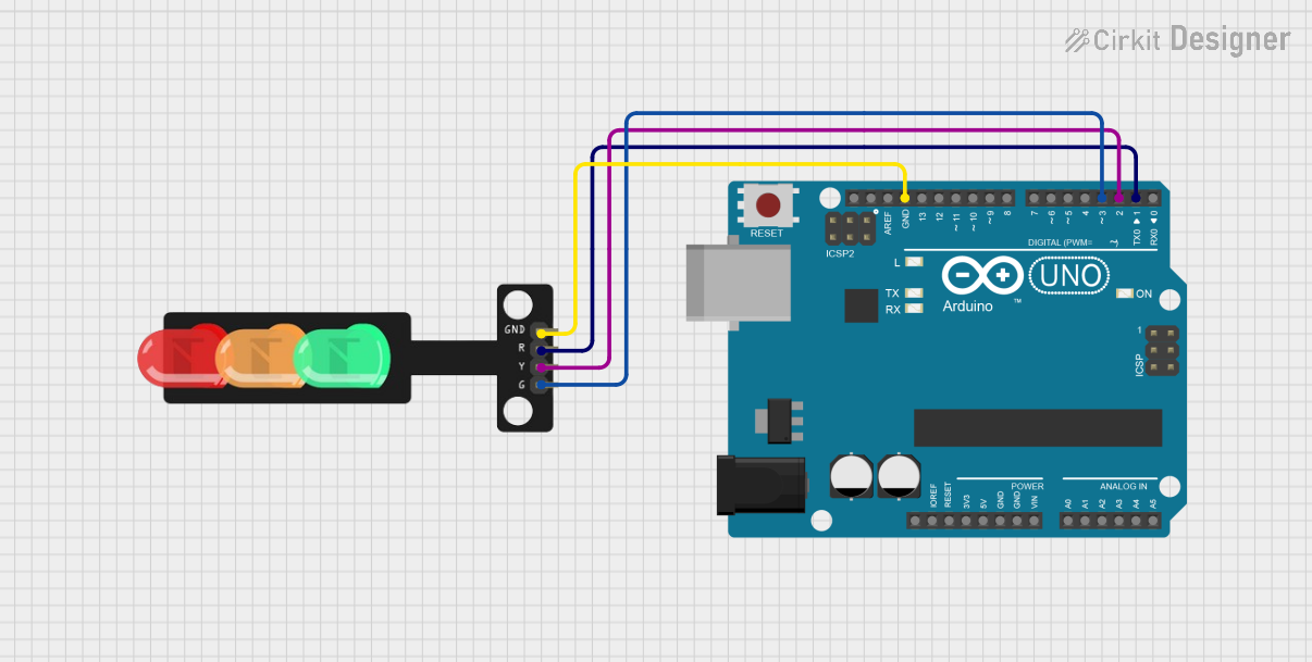
Connect the Pins:
- Connect the Red, Yellow, and Green LED pins to three separate digital output pins on the Arduino UNO.
- Connect the Ground (GND) pin of the Traffic Light module to the GND pin on the Arduino UNO.
Add Resistors (if required):
- Use 220Ω resistors in series with each LED pin to limit current and prevent damage to the LEDs.
Power the Circuit:
- Ensure the Arduino UNO is powered via USB or an external power source.
Write and Upload Code:
- Use the Arduino IDE to write a program that controls the Traffic Light sequence (e.g., red → yellow → green).
Important Considerations and Best Practices
- Power Supply: Ensure the module operates at 5V DC to avoid damaging the LEDs.
- Timing: Use appropriate delays in your code to simulate realistic traffic light timing.
- Resistors: Always use current-limiting resistors to protect the LEDs.
- Testing: Test the circuit on a breadboard before finalizing the design.
Example Code for Arduino UNO
Below is an example code to simulate a basic traffic light sequence:
// Pin assignments for the Traffic Light module
const int redPin = 8;    // Red LED connected to digital pin 8
const int yellowPin = 9; // Yellow LED connected to digital pin 9
const int greenPin = 10; // Green LED connected to digital pin 10

void setup() {
  // Set the LED pins as outputs
  pinMode(redPin, OUTPUT);
  pinMode(yellowPin, OUTPUT);
  pinMode(greenPin, OUTPUT);
}

void loop() {
  // Turn on the red light and wait for 5 seconds
  digitalWrite(redPin, HIGH);
  delay(5000); // 5000ms = 5 seconds
  digitalWrite(redPin, LOW);

  // Turn on the yellow light and wait for 2 seconds
  digitalWrite(yellowPin, HIGH);
  delay(2000); // 2000ms = 2 seconds
  digitalWrite(yellowPin, LOW);

  // Turn on the green light and wait for 5 seconds
  digitalWrite(greenPin, HIGH);
  delay(5000); // 5000ms = 5 seconds
  digitalWrite(greenPin, LOW);
}
Code Explanation
- The
setup()function initializes the LED pins as outputs. - The
loop()function cycles through the red, yellow, and green lights with appropriate delays to simulate a traffic light sequence.
Troubleshooting and FAQs
Common Issues and Solutions
LEDs Not Lighting Up:
- Cause: Incorrect wiring or loose connections.
- Solution: Double-check the wiring and ensure all connections are secure.
LEDs Too Dim or Not Working:
- Cause: Missing or incorrect resistors.
- Solution: Use 220Ω resistors in series with each LED pin.
Incorrect Light Sequence:
- Cause: Errors in the code logic.
- Solution: Verify the code and ensure the correct pins are assigned to each LED.
Arduino Not Responding:
- Cause: Faulty USB connection or incorrect board selection in the Arduino IDE.
- Solution: Check the USB cable, select the correct board and port in the Arduino IDE, and re-upload the code.
FAQs
Q1: Can I use this Traffic Light module with other microcontrollers?
A1: Yes, the module can be used with other 5V-compatible microcontrollers, but you may need to adjust the code accordingly.
Q2: How can I add a pedestrian crossing signal?
A2: You can add additional LEDs and control them using extra digital pins on the Arduino UNO. Modify the code to include the pedestrian signal logic.
Q3: Can I power the Traffic Light module with a battery?
A3: Yes, you can use a 5V battery pack, but ensure the total current draw does not exceed the battery's capacity.
Q4: How do I simulate a blinking yellow light?
A4: Use the digitalWrite() and delay() functions in a loop to toggle the yellow LED on and off at regular intervals.
By following this documentation, you can effectively use the Traffic Light module in your projects and troubleshoot common issues with ease.