Cirkit Designer Logo
Cirkit Designer
Your all-in-one circuit design IDE
Home / 
Component Documentation

How to Use s: Examples, Pinouts, and Specs

Image of s
Cirkit Designer LogoDesign with s in Cirkit Designer

Introduction

A switch, often denoted as "S" in circuit diagrams, is an essential electronic component used to control the flow of electrical current in a circuit. By opening or closing the circuit, a switch either allows or interrupts the flow of current, enabling or disabling the operation of connected devices. Switches come in various types, including toggle, push-button, slide, rotary, and more, each suited for specific applications.

Explore Projects Built with s

Use Cirkit Designer to design, explore, and prototype these projects online. Some projects support real-time simulation. Click "Open Project" to start designing instantly!
NFC-Enabled Access Control System with Real-Time Clock and OLED Display
Image of doorlock: A project utilizing s in a practical application
This circuit is designed as an access control system with time-tracking capabilities. It uses an NFC/RFID reader for authentication, a real-time clock for time-stamping events, and an OLED display for user interface, all controlled by a T8_S3 microcontroller. A relay module actuates a magnetic lock, and a button switch provides additional user input, with a switching power supply delivering the necessary voltages.
Cirkit Designer LogoOpen Project in Cirkit Designer
NFC-Enabled Access Control System with Time Logging
Image of doorlock: A project utilizing s in a practical application
This circuit is designed for access control with time tracking capabilities. It features an NFC/RFID reader for authentication, an RTC module (DS3231) for real-time clock functionality, and an OLED display for user interaction. A 12V relay controls a magnetic lock, which is activated upon successful NFC/RFID authentication, and a button switch is likely used for manual operation or input. The T8_S3 microcontroller serves as the central processing unit, interfacing with the NFC/RFID reader, RTC, OLED, and relay to manage the access control logic.
Cirkit Designer LogoOpen Project in Cirkit Designer
Beelink Mini S12 N95 and Arduino UNO Based Fingerprint Authentication System with ESP32 CAM
Image of design 3: A project utilizing s in a practical application
This circuit features a Beelink MINI S12 N95 computer connected to a 7-inch display via HDMI for video output and two USB connections for power and touch screen functionality. An Arduino UNO is interfaced with a fingerprint scanner for biometric input. The Beelink MINI S12 N95 is powered by a PC power supply, which in turn is connected to a 240V power source. Additionally, an ESP32 CAM module is powered and programmed via a USB plug and an FTDI programmer, respectively, for wireless camera capabilities.
Cirkit Designer LogoOpen Project in Cirkit Designer
ESP32-S3 Based Vibration Detection System with TFT Display and Power Backup
Image of IOT Thesis: A project utilizing s in a practical application
This circuit features an ESP32-S3 microcontroller connected to various peripherals including an ADXL355 accelerometer, an SW-420 vibration sensor, a buzzer module, and an ILI9341 TFT display. The ESP32-S3 manages sensor inputs and provides output to the display and buzzer. Power management is handled by a 12V to 5V step-down converter, and a UPS ensures uninterrupted power supply, with a rocker switch to control the power flow.
Cirkit Designer LogoOpen Project in Cirkit Designer

Explore Projects Built with s

Use Cirkit Designer to design, explore, and prototype these projects online. Some projects support real-time simulation. Click "Open Project" to start designing instantly!
Image of doorlock: A project utilizing s in a practical application
NFC-Enabled Access Control System with Real-Time Clock and OLED Display
This circuit is designed as an access control system with time-tracking capabilities. It uses an NFC/RFID reader for authentication, a real-time clock for time-stamping events, and an OLED display for user interface, all controlled by a T8_S3 microcontroller. A relay module actuates a magnetic lock, and a button switch provides additional user input, with a switching power supply delivering the necessary voltages.
Cirkit Designer LogoOpen Project in Cirkit Designer
Image of doorlock: A project utilizing s in a practical application
NFC-Enabled Access Control System with Time Logging
This circuit is designed for access control with time tracking capabilities. It features an NFC/RFID reader for authentication, an RTC module (DS3231) for real-time clock functionality, and an OLED display for user interaction. A 12V relay controls a magnetic lock, which is activated upon successful NFC/RFID authentication, and a button switch is likely used for manual operation or input. The T8_S3 microcontroller serves as the central processing unit, interfacing with the NFC/RFID reader, RTC, OLED, and relay to manage the access control logic.
Cirkit Designer LogoOpen Project in Cirkit Designer
Image of design 3: A project utilizing s in a practical application
Beelink Mini S12 N95 and Arduino UNO Based Fingerprint Authentication System with ESP32 CAM
This circuit features a Beelink MINI S12 N95 computer connected to a 7-inch display via HDMI for video output and two USB connections for power and touch screen functionality. An Arduino UNO is interfaced with a fingerprint scanner for biometric input. The Beelink MINI S12 N95 is powered by a PC power supply, which in turn is connected to a 240V power source. Additionally, an ESP32 CAM module is powered and programmed via a USB plug and an FTDI programmer, respectively, for wireless camera capabilities.
Cirkit Designer LogoOpen Project in Cirkit Designer
Image of IOT Thesis: A project utilizing s in a practical application
ESP32-S3 Based Vibration Detection System with TFT Display and Power Backup
This circuit features an ESP32-S3 microcontroller connected to various peripherals including an ADXL355 accelerometer, an SW-420 vibration sensor, a buzzer module, and an ILI9341 TFT display. The ESP32-S3 manages sensor inputs and provides output to the display and buzzer. Power management is handled by a 12V to 5V step-down converter, and a UPS ensures uninterrupted power supply, with a rocker switch to control the power flow.
Cirkit Designer LogoOpen Project in Cirkit Designer

Common Applications and Use Cases

  • Power Control: Turning devices on or off, such as lights, fans, or appliances.
  • Signal Control: Switching between different signal paths in audio or communication systems.
  • User Input: Acting as an interface in devices like keyboards, remote controls, and gaming controllers.
  • Safety Mechanisms: Emergency stop buttons in industrial equipment.
  • Mode Selection: Changing operational modes in electronic devices.

Technical Specifications

The technical specifications of a switch depend on its type and intended application. Below are general specifications for a standard toggle or push-button switch:

General Specifications

  • Voltage Rating: 3V to 250V (AC or DC, depending on the switch type)
  • Current Rating: 0.1A to 15A
  • Contact Resistance: Typically < 50 mΩ
  • Insulation Resistance: > 100 MΩ at 500V DC
  • Mechanical Life: 10,000 to 1,000,000 operations (varies by type)
  • Operating Temperature: -20°C to +85°C

Pin Configuration and Descriptions

The pin configuration of a switch depends on its type. Below is an example for a Single Pole Single Throw (SPST) switch and a Single Pole Double Throw (SPDT) switch.

SPST Switch

Pin Number Description
1 Input terminal (connect to VCC)
2 Output terminal (connect to load)

SPDT Switch

Pin Number Description
1 Common terminal (COM)
2 Normally Open (NO) terminal
3 Normally Closed (NC) terminal

Usage Instructions

How to Use the Component in a Circuit

  1. Identify the Switch Type: Determine whether the switch is SPST, SPDT, or another type.
  2. Connect the Terminals:
    • For an SPST switch, connect one terminal to the power source and the other to the load.
    • For an SPDT switch, connect the common terminal to the power source, and the NO/NC terminals to the desired outputs.
  3. Secure the Switch: Mount the switch securely in its intended location to ensure reliable operation.
  4. Test the Circuit: Verify that the switch operates as expected by toggling it and observing the circuit's behavior.

Important Considerations and Best Practices

  • Voltage and Current Ratings: Ensure the switch's ratings match or exceed the circuit's requirements to avoid damage or failure.
  • Debouncing: Mechanical switches may produce noise or "bouncing" when toggled. Use a capacitor or software debouncing techniques in microcontroller applications.
  • Safety: For high-voltage or high-current applications, use switches with appropriate insulation and safety certifications.
  • Environmental Factors: Choose switches with suitable IP ratings for outdoor or harsh environments.

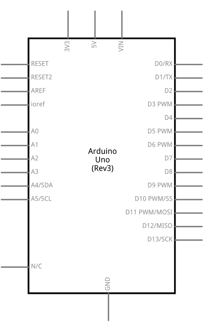
Example: Connecting a Switch to an Arduino UNO

Below is an example of how to connect an SPST switch to an Arduino UNO to control an LED.

Circuit Diagram

  • Connect one terminal of the switch to Arduino pin 2.
  • Connect the other terminal of the switch to GND.
  • Use a pull-up resistor (10kΩ) between pin 2 and VCC to ensure a stable input signal.

Arduino Code

// Define pin numbers
const int switchPin = 2;  // Pin connected to the switch
const int ledPin = 13;    // Pin connected to the onboard LED

void setup() {
  pinMode(switchPin, INPUT_PULLUP); // Set switch pin as input with pull-up resistor
  pinMode(ledPin, OUTPUT);          // Set LED pin as output
}

void loop() {
  int switchState = digitalRead(switchPin); // Read the state of the switch

  if (switchState == LOW) { // If the switch is pressed (LOW due to pull-up)
    digitalWrite(ledPin, HIGH); // Turn on the LED
  } else {
    digitalWrite(ledPin, LOW);  // Turn off the LED
  }
}

Troubleshooting and FAQs

Common Issues Users Might Face

  1. Switch Not Working:

    • Cause: Incorrect wiring or loose connections.
    • Solution: Double-check the wiring and ensure all connections are secure.
  2. Switch Bouncing:

    • Cause: Mechanical noise when toggling the switch.
    • Solution: Use a capacitor for hardware debouncing or implement software debouncing in your code.
  3. Overheating or Damage:

    • Cause: Exceeding the switch's voltage or current ratings.
    • Solution: Use a switch with appropriate ratings for your circuit.
  4. No Response in Arduino Circuit:

    • Cause: Missing pull-up or pull-down resistor.
    • Solution: Add a pull-up or pull-down resistor to stabilize the input signal.

FAQs

Q1: Can I use a switch to control AC devices?
A1: Yes, but ensure the switch is rated for the AC voltage and current. For high-power devices, consider using a relay in conjunction with the switch.

Q2: What is the difference between NO and NC terminals in an SPDT switch?
A2: The NO (Normally Open) terminal is disconnected when the switch is in its default state, while the NC (Normally Closed) terminal is connected in the default state.

Q3: How do I debounce a switch in software?
A3: Use a delay or a state-checking algorithm in your code to filter out rapid changes in the switch's state caused by bouncing.

By following this documentation, you can effectively integrate and troubleshoot switches in your electronic projects.