How to Use Si7021: Examples, Pinouts, and Specs
Introduction
The Si7021, manufactured by Adafruit (Part ID: Humidity Temp), is a digital humidity and temperature sensor designed for precise environmental monitoring. It provides accurate measurements of relative humidity and temperature while consuming minimal power, making it suitable for battery-powered and energy-efficient applications. The sensor communicates via an I2C interface, ensuring seamless integration into microcontroller-based systems.
Explore Projects Built with Si7021


Explore Projects Built with Si7021
Common Applications
- Environmental monitoring systems
- HVAC (Heating, Ventilation, and Air Conditioning) systems
- Weather stations
- IoT (Internet of Things) devices
- Industrial and home automation
Technical Specifications
Key Technical Details
| Parameter | Value |
|---|---|
| Supply Voltage | 1.9V to 3.6V |
| Typical Operating Voltage | 3.3V |
| Current Consumption | 150 µA (typical) |
| Humidity Range | 0% to 100% RH |
| Humidity Accuracy | ±3% RH (typical) |
| Temperature Range | -40°C to +125°C |
| Temperature Accuracy | ±0.4°C (typical) |
| Communication Interface | I2C |
| I2C Address | 0x40 (default) |
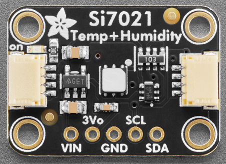
Pin Configuration
The Si7021 sensor is typically available on a breakout board with the following pinout:
| Pin Name | Description |
|---|---|
| VIN | Power supply input (1.9V to 3.6V) |
| GND | Ground |
| SDA | I2C data line |
| SCL | I2C clock line |
Usage Instructions
Connecting the Si7021 to an Arduino UNO
To use the Si7021 with an Arduino UNO, follow these steps:
- Connect the VIN pin of the Si7021 to the 3.3V pin on the Arduino.
- Connect the GND pin of the Si7021 to the GND pin on the Arduino.
- Connect the SDA pin of the Si7021 to the A4 pin on the Arduino (I2C data line).
- Connect the SCL pin of the Si7021 to the A5 pin on the Arduino (I2C clock line).
Arduino Code Example
Below is an example Arduino sketch to read humidity and temperature data from the Si7021 sensor:
#include <Wire.h>
#include "Adafruit_Si7021.h"

// Create an instance of the Si7021 sensor
Adafruit_Si7021 sensor = Adafruit_Si7021();

void setup() {
  Serial.begin(9600); // Initialize serial communication
  Serial.println("Si7021 Sensor Test");

  // Initialize the sensor
  if (!sensor.begin()) {
    Serial.println("Sensor not found. Check wiring!");
    while (true); // Halt execution if sensor is not detected
  }
  Serial.println("Sensor initialized successfully.");
}

void loop() {
  // Read humidity and temperature
  float humidity = sensor.readHumidity();
  float temperature = sensor.readTemperature();

  // Print the readings to the Serial Monitor
  Serial.print("Humidity: ");
  Serial.print(humidity);
  Serial.println(" %");

  Serial.print("Temperature: ");
  Serial.print(temperature);
  Serial.println(" °C");

  delay(2000); // Wait 2 seconds before the next reading
}
Important Considerations
- Ensure the sensor is powered within its operating voltage range (1.9V to 3.6V).
- Avoid exposing the sensor to extreme conditions (e.g., condensation or high humidity for prolonged periods) to maintain accuracy.
- Use pull-up resistors (typically 4.7kΩ) on the SDA and SCL lines if they are not already included on the breakout board.
Troubleshooting and FAQs
Common Issues and Solutions
Sensor not detected by the Arduino:
- Verify the wiring connections, especially the SDA and SCL lines.
- Ensure the I2C address (default: 0x40) matches the one used in your code.
- Check if pull-up resistors are required on the I2C lines.
Incorrect or fluctuating readings:
- Ensure the sensor is not exposed to rapid temperature or humidity changes.
- Avoid placing the sensor near heat sources or in direct sunlight.
- Verify that the power supply voltage is stable and within the specified range.
Code compilation errors:
- Ensure the Adafruit Si7021 library is installed in the Arduino IDE. You can install it via the Library Manager.
FAQs
Q: Can the Si7021 measure dew point?
A: The Si7021 does not directly measure dew point, but you can calculate it using the humidity and temperature readings with appropriate formulas.
Q: Is the Si7021 waterproof?
A: No, the Si7021 is not waterproof. Avoid exposing it to water or condensation.
Q: Can I use the Si7021 with a 5V microcontroller?
A: Yes, but you must use a logic level shifter to step down the I2C signals to 3.3V, as the Si7021 operates at 3.3V logic levels.
By following this documentation, you can effectively integrate the Si7021 sensor into your projects for reliable humidity and temperature measurements.