
How to Use Rotary Encoder: Examples, Pinouts, and Specs
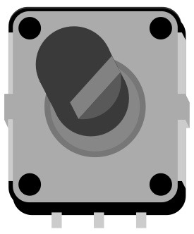
 Design with Rotary Encoder in Cirkit Designer
Introduction
The Alps Alpine STEC12E07 is a high-quality rotary encoder designed to convert the angular position or motion of a shaft into a digital signal. This electromechanical device is widely used in applications requiring precise position sensing, user input control, or rotational feedback. Its compact design and robust performance make it ideal for use in industrial equipment, consumer electronics, and robotics.
Explore Projects Built with Rotary Encoder
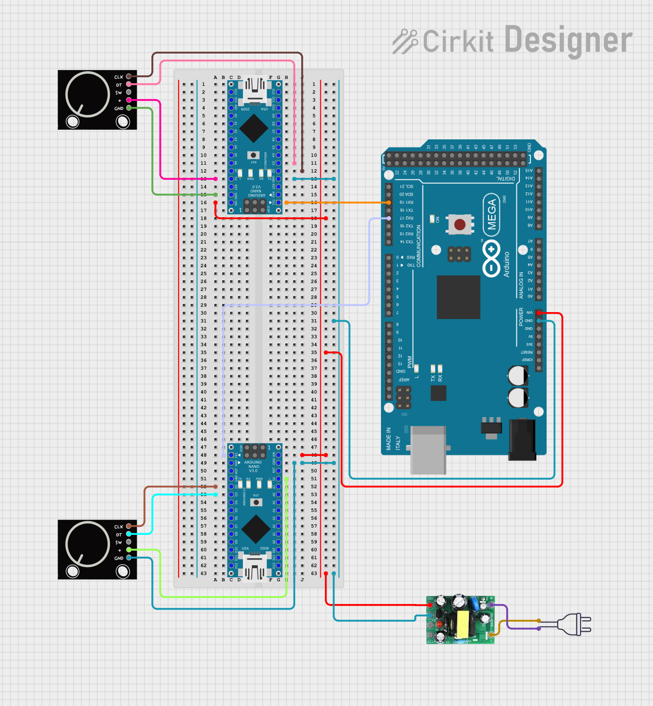 Open Project in Cirkit Designer
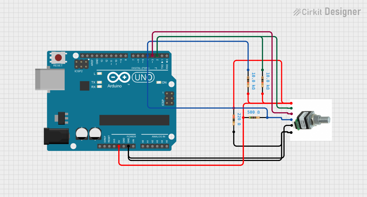 Open Project in Cirkit Designer
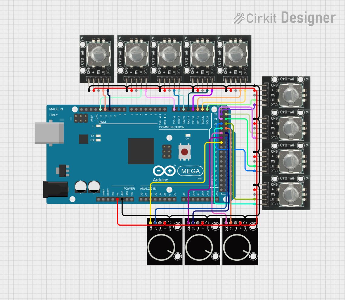 Open Project in Cirkit Designer
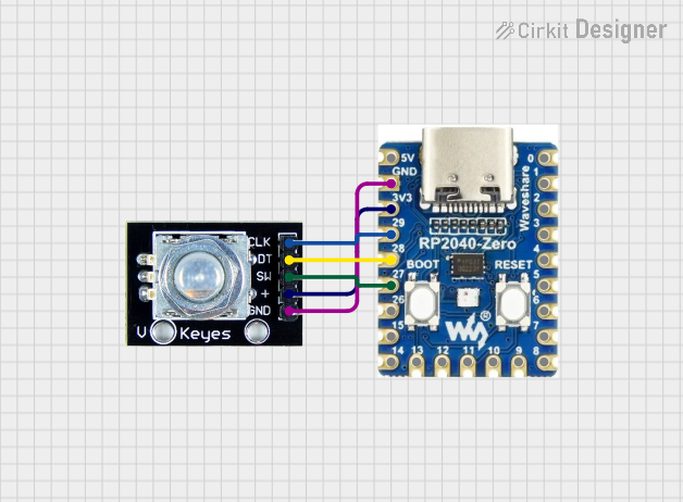 Open Project in Cirkit Designer
Explore Projects Built with Rotary Encoder
Open Project in Cirkit DesignerOpen Project in Cirkit DesignerOpen Project in Cirkit DesignerOpen Project in Cirkit DesignerCommon Applications
- Volume and menu control in audio and video equipment
- Position sensing in industrial machinery
- User input for microcontroller-based projects
- Robotics and automation systems
- Motor speed and direction control
Technical Specifications
The following table outlines the key technical details of the STEC12E07 rotary encoder:
| Parameter | Specification |
|---|---|
| Manufacturer | Alps Alpine |
| Part Number | STEC12E07 |
| Operating Voltage | 5V DC |
| Maximum Current | 10 mA |
| Output Type | Quadrature (2-bit Gray Code) |
| Rotational Life | 30,000 cycles |
| Detent Positions | 30 |
| Pulses per Revolution | 15 |
| Operating Temperature | -30°C to +85°C |
| Shaft Length | 15 mm |
| Mounting Style | PCB Mount |
Pin Configuration and Descriptions
The STEC12E07 rotary encoder has five pins. The table below describes each pin:
| Pin Number | Pin Name | Description |
|---|---|---|
| 1 | GND | Ground connection |
| 2 | VCC | Power supply (typically 5V DC) |
| 3 | SW | Push-button switch output (active low) |
| 4 | DT | Data signal for quadrature output |
| 5 | CLK | Clock signal for quadrature output |
Usage Instructions
How to Use the Rotary Encoder in a Circuit
- Power Connections: Connect the
VCCpin to a 5V DC power source and theGNDpin to ground. - Signal Connections: Connect the
CLKandDTpins to digital input pins on your microcontroller. These pins provide the quadrature signals for detecting rotation direction and steps. - Push-Button Connection: Connect the
SWpin to a digital input pin on your microcontroller. Use a pull-up resistor if necessary, as the switch output is active low. - Debouncing: Implement software or hardware debouncing to ensure reliable signal readings, as mechanical contacts may produce noise.
Important Considerations
- Debouncing: Rotary encoders can produce noisy signals due to mechanical bouncing. Use software debouncing or external capacitors to filter out noise.
- Pull-Up Resistors: Ensure pull-up resistors are used for the
SW,CLK, andDTpins if your microcontroller does not have internal pull-ups enabled. - Signal Timing: Read the
CLKandDTsignals carefully to determine the direction and number of steps. The quadrature output provides two signals that are 90° out of phase.
Example Code for Arduino UNO
Below is an example Arduino sketch to read the STEC12E07 rotary encoder and detect rotation direction and button presses:
// Pin definitions for the rotary encoder
#define CLK 2  // Clock pin connected to digital pin 2
#define DT 3   // Data pin connected to digital pin 3
#define SW 4   // Switch pin connected to digital pin 4

int lastStateCLK;  // Variable to store the previous state of the CLK pin
int currentStateCLK;  // Variable to store the current state of the CLK pin
int counter = 0;  // Counter to track the encoder position
String direction;  // Variable to store the rotation direction

void setup() {
  pinMode(CLK, INPUT);  // Set CLK pin as input
  pinMode(DT, INPUT);   // Set DT pin as input
  pinMode(SW, INPUT_PULLUP);  // Set SW pin as input with pull-up resistor

  // Read the initial state of the CLK pin
  lastStateCLK = digitalRead(CLK);

  // Initialize serial communication for debugging
  Serial.begin(9600);
}

void loop() {
  // Read the current state of the CLK pin
  currentStateCLK = digitalRead(CLK);

  // If the state of the CLK pin has changed, a step has occurred
  if (currentStateCLK != lastStateCLK) {
    // Check the state of the DT pin to determine the direction
    if (digitalRead(DT) != currentStateCLK) {
      counter++;  // Clockwise rotation
      direction = "CW";
    } else {
      counter--;  // Counterclockwise rotation
      direction = "CCW";
    }

    // Print the direction and counter value to the serial monitor
    Serial.print("Direction: ");
    Serial.print(direction);
    Serial.print(" | Counter: ");
    Serial.println(counter);
  }

  // Update the last state of the CLK pin
  lastStateCLK = currentStateCLK;

  // Check if the push-button is pressed
  if (digitalRead(SW) == LOW) {
    Serial.println("Button Pressed!");
    delay(200);  // Debounce delay
  }
}
Troubleshooting and FAQs
Common Issues
No Signal Detected:
- Ensure the
VCCandGNDpins are properly connected. - Verify that the
CLKandDTpins are connected to the correct microcontroller pins. - Check for loose or faulty connections.
- Ensure the
Erratic or Noisy Readings:
- Implement software debouncing in your code.
- Add a small capacitor (e.g., 0.1 µF) between the
CLKandGNDpins and between theDTandGNDpins to filter noise.
Push-Button Not Working:
- Verify the
SWpin connection and ensure a pull-up resistor is used. - Check if the button is physically stuck or damaged.
- Verify the
FAQs
Q: Can I use the STEC12E07 with a 3.3V microcontroller?
A: Yes, the STEC12E07 can work with 3.3V systems, but ensure the signal levels are compatible with your microcontroller.
Q: How do I increase the rotational life of the encoder?
A: Avoid applying excessive force to the shaft and ensure the encoder is mounted securely to prevent mechanical stress.
Q: What is the purpose of the detent positions?
A: Detent positions provide tactile feedback, making it easier to feel discrete steps during rotation.
Q: Can I use this encoder for high-speed applications?
A: The STEC12E07 is suitable for low to moderate-speed applications. For high-speed use, consider encoders designed specifically for such purposes.