Cirkit Designer Logo
Cirkit Designer
Your all-in-one circuit design IDE
Home / 
Component Documentation

How to Use Adafruit RGB Matrix Shield for Arduino: Examples, Pinouts, and Specs

Image of Adafruit RGB Matrix Shield for Arduino
Cirkit Designer LogoDesign with Adafruit RGB Matrix Shield for Arduino in Cirkit Designer

Introduction

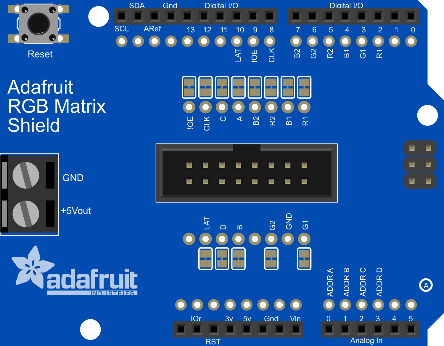
The Adafruit RGB Matrix Shield for Arduino is a versatile and user-friendly shield designed to drive RGB LED matrix panels with ease. This shield is an ideal choice for hobbyists and professionals looking to create vibrant displays for signage, visual effects, or interactive art installations. Common applications include message boards, digital art, gaming displays, and educational projects.

Explore Projects Built with Adafruit RGB Matrix Shield for Arduino

Use Cirkit Designer to design, explore, and prototype these projects online. Some projects support real-time simulation. Click "Open Project" to start designing instantly!
Arduino-Based Temperature Monitoring System with RGB LED Feedback and I2C LCD Display
Image of wemos custom shield: A project utilizing Adafruit RGB Matrix Shield for Arduino in a practical application
This circuit features an Adafruit Proto Shield R3 configured with a DS18B20 temperature sensor, a WS2812 RGB LED matrix, and an LCD I2C display. The microcontroller on the Proto Shield reads the temperature from the DS18B20 sensor and displays it on the LCD. It also controls the LED matrix to show random colors and indicates temperature status with onboard LEDs.
Cirkit Designer LogoOpen Project in Cirkit Designer
Arduino-Controlled RGB LED Matrix Display
Image of SMD2121 Led screen: A project utilizing Adafruit RGB Matrix Shield for Arduino in a practical application
This circuit connects an Arduino UNO R4 WiFi microcontroller to a 64x32 LED matrix display. The Arduino is configured to control the LED matrix, sending color data and control signals to display various colors across the matrix. The embedded code on the Arduino cycles through a range of colors, filling the entire LED matrix with each color in sequence.
Cirkit Designer LogoOpen Project in Cirkit Designer
Arduino UNO WiFi-Controlled LED Matrix Display
Image of SMD2121 Led screen - r4: A project utilizing Adafruit RGB Matrix Shield for Arduino in a practical application
This circuit consists of an Arduino UNO R4 WiFi microcontroller connected to a 64x32 LED matrix. The Arduino controls the LED matrix by sending signals to various pins to display different colors and patterns, as defined in the embedded code.
Cirkit Designer LogoOpen Project in Cirkit Designer
Arduino UNO Controlled LED Matrix and LCD Interface with Joystick Interaction
Image of Digital Game Circuit: A project utilizing Adafruit RGB Matrix Shield for Arduino in a practical application
This circuit features an Arduino UNO microcontroller interfaced with an 8x8 LED matrix, an LCD screen, and a KY-023 Dual Axis Joystick Module. The Arduino controls the LED matrix via digital pins D10-D12 and powers the matrix, LCD, and joystick module from its 5V output. The joystick's analog outputs are connected to the Arduino's analog inputs A0 and A1 for position sensing, while the LCD is controlled through digital pins D2-D6 and D13 for display purposes.
Cirkit Designer LogoOpen Project in Cirkit Designer

Explore Projects Built with Adafruit RGB Matrix Shield for Arduino

Use Cirkit Designer to design, explore, and prototype these projects online. Some projects support real-time simulation. Click "Open Project" to start designing instantly!
Image of wemos custom shield: A project utilizing Adafruit RGB Matrix Shield for Arduino in a practical application
Arduino-Based Temperature Monitoring System with RGB LED Feedback and I2C LCD Display
This circuit features an Adafruit Proto Shield R3 configured with a DS18B20 temperature sensor, a WS2812 RGB LED matrix, and an LCD I2C display. The microcontroller on the Proto Shield reads the temperature from the DS18B20 sensor and displays it on the LCD. It also controls the LED matrix to show random colors and indicates temperature status with onboard LEDs.
Cirkit Designer LogoOpen Project in Cirkit Designer
Image of SMD2121 Led screen: A project utilizing Adafruit RGB Matrix Shield for Arduino in a practical application
Arduino-Controlled RGB LED Matrix Display
This circuit connects an Arduino UNO R4 WiFi microcontroller to a 64x32 LED matrix display. The Arduino is configured to control the LED matrix, sending color data and control signals to display various colors across the matrix. The embedded code on the Arduino cycles through a range of colors, filling the entire LED matrix with each color in sequence.
Cirkit Designer LogoOpen Project in Cirkit Designer
Image of SMD2121 Led screen - r4: A project utilizing Adafruit RGB Matrix Shield for Arduino in a practical application
Arduino UNO WiFi-Controlled LED Matrix Display
This circuit consists of an Arduino UNO R4 WiFi microcontroller connected to a 64x32 LED matrix. The Arduino controls the LED matrix by sending signals to various pins to display different colors and patterns, as defined in the embedded code.
Cirkit Designer LogoOpen Project in Cirkit Designer
Image of Digital Game Circuit: A project utilizing Adafruit RGB Matrix Shield for Arduino in a practical application
Arduino UNO Controlled LED Matrix and LCD Interface with Joystick Interaction
This circuit features an Arduino UNO microcontroller interfaced with an 8x8 LED matrix, an LCD screen, and a KY-023 Dual Axis Joystick Module. The Arduino controls the LED matrix via digital pins D10-D12 and powers the matrix, LCD, and joystick module from its 5V output. The joystick's analog outputs are connected to the Arduino's analog inputs A0 and A1 for position sensing, while the LCD is controlled through digital pins D2-D6 and D13 for display purposes.
Cirkit Designer LogoOpen Project in Cirkit Designer

Technical Specifications

Key Technical Details

  • Operating Voltage: 5V (from Arduino)
  • Supported Panels: 16x32, 32x32, or 64x32 RGB LED matrices
  • Output Connectors: 2x8 IDC
  • Arduino Compatibility: Uno, Mega, and similar form factor boards

Pin Configuration and Descriptions

Pin Number Function Description
1 GND Ground
2 CLK Clock signal for the LED matrix
3 OE Output enable, active low
4 LAT Latch signal, controls when data is latched
5 A Row address line A
6 B Row address line B
7 C Row address line C
8 D Row address line D (for 1/32 scan matrices)
9 R1 Red data line for the top half of the display
10 G1 Green data line for the top half of the display
11 B1 Blue data line for the top half of the display
12 R2 Red data line for the bottom half of the display
13 G2 Green data line for the bottom half of the display
14 B2 Blue data line for the bottom half of the display
15 5V 5V power from Arduino
16 GND Ground

Usage Instructions

Connecting the Shield to an Arduino

  1. Align the shield's pins with the corresponding headers on the Arduino board.
  2. Gently press down to mate the connectors, ensuring a snug fit without bending any pins.

Connecting the RGB LED Matrix

  1. Use the provided ribbon cable to connect the shield's IDC connectors to the RGB LED matrix.
  2. Ensure the cable's orientation matches the markings on the shield and the matrix.

Programming the Arduino

To control the RGB LED matrix, you will need to install the Adafruit RGB Matrix Panel library. This can be done through the Arduino Library Manager:

  1. Open the Arduino IDE.
  2. Go to Sketch > Include Library > Manage Libraries....
  3. Search for "RGB matrix Panel" and install the Adafruit RGB Matrix Panel library.

Here is a simple example code to display a static color on the matrix:

#include <Adafruit_GFX.h>   // Core graphics library
#include <RGBmatrixPanel.h> // Hardware-specific library

#define CLK  8  // MUST be on PORTB! (Use pin 11 on Mega)
#define OE   9
#define LAT 10
#define A   A0
#define B   A1
#define C   A2
#define D   A3 // Only required for 32x32 panels

// 16x32 panel:
RGBmatrixPanel matrix(A, B, C, CLK, LAT, OE, false);
// 32x32 panel:
//RGBmatrixPanel matrix(A, B, C, D, CLK, LAT, OE, false);

void setup() {
  matrix.begin();
  matrix.fillScreen(matrix.Color333(7, 0, 0)); // Fill screen with solid red
}

void loop() {
  // Code to animate or change display goes here
}

Important Considerations and Best Practices

  • Ensure the power supply can handle the current draw of the LED matrix, especially for larger displays.
  • Avoid making connections or disconnections to the shield while the Arduino is powered to prevent damage.
  • Use capacitors as recommended in the Adafruit guide to smooth out power supply noise.

Troubleshooting and FAQs

Common Issues

  • Display is not lighting up: Check all connections, ensure the power supply is adequate, and verify that the correct pins are used in the code.
  • Flickering or erratic behavior: This may be due to power supply issues. Ensure that the power supply is stable and of sufficient capacity.

Solutions and Tips for Troubleshooting

  • Double-check the wiring against the pin configuration table.
  • Make sure the library is correctly installed and included in your sketch.
  • Review the example sketches provided with the library for reference.
  • If using a larger matrix, consider using an external power supply to provide sufficient current.

FAQs

Q: Can I chain multiple panels together? A: Yes, the shield supports daisy-chaining panels. You will need to adjust the code to accommodate the increased resolution.

Q: Is the shield compatible with Arduino Nano? A: The shield is designed for Arduino Uno and Mega form factors. It may not be directly compatible with the Nano due to the different pin layout.

Q: Can I use this shield with other microcontrollers? A: While the shield is designed for Arduino, it may be possible to use it with other microcontrollers if they have compatible GPIO and you can port the library.

Remember to always refer to the official Adafruit documentation and forums for more detailed information and support.