
How to Use STC-1000: Examples, Pinouts, and Specs
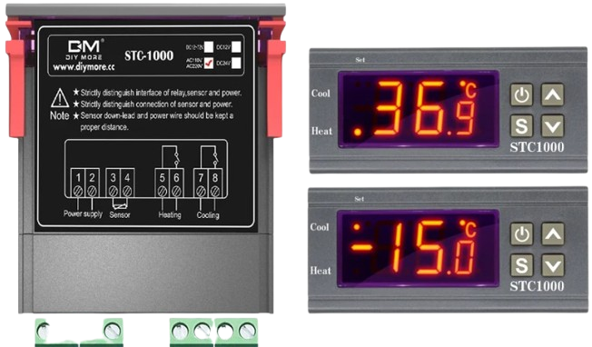
 Design with STC-1000 in Cirkit Designer
Introduction
The STC-1000 is a versatile digital temperature controller manufactured by SMKN1GEMPOL (Part ID: SMKN1GEMPOL). It is widely used in refrigeration, heating, and other temperature-sensitive applications. The device is equipped with a dual relay output, enabling it to control both heating and cooling systems. With its built-in temperature sensor input and intuitive interface, the STC-1000 allows users to set and maintain precise temperature ranges with ease.
Explore Projects Built with STC-1000
 Open Project in Cirkit Designer
 Open Project in Cirkit Designer
 Open Project in Cirkit Designer
 Open Project in Cirkit Designer
Explore Projects Built with STC-1000
Open Project in Cirkit DesignerOpen Project in Cirkit DesignerOpen Project in Cirkit DesignerOpen Project in Cirkit DesignerCommon Applications
- Refrigeration systems for food storage
- Incubators for hatching eggs
- Aquariums and terrariums
- Home brewing and fermentation processes
- HVAC systems for temperature regulation
Technical Specifications
Key Technical Details
| Parameter | Specification |
|---|---|
| Operating Voltage | 110V AC or 220V AC (±10%) |
| Temperature Range | -50°C to 99°C (-58°F to 210°F) |
| Temperature Accuracy | ±1°C (±2°F) |
| Sensor Type | NTC (10kΩ) |
| Relay Output (Heating) | 10A at 220V AC |
| Relay Output (Cooling) | 10A at 220V AC |
| Power Consumption | ≤3W |
| Operating Temperature | -10°C to 60°C (14°F to 140°F) |
| Storage Temperature | -20°C to 75°C (-4°F to 167°F) |
| Dimensions | 75mm x 34.5mm x 85mm |
Pin Configuration and Descriptions
| Pin Number | Label | Description |
|---|---|---|
| 1 | Power (L) | Live wire input for AC power supply |
| 2 | Power (N) | Neutral wire input for AC power supply |
| 3 | Cooling (NO) | Normally open terminal for cooling relay output |
| 4 | Cooling (COM) | Common terminal for cooling relay output |
| 5 | Heating (NO) | Normally open terminal for heating relay output |
| 6 | Heating (COM) | Common terminal for heating relay output |
| 7 | Sensor Input | Connects to the NTC temperature sensor |
| 8 | Sensor Input | Connects to the NTC temperature sensor (polarity-independent) |
Usage Instructions
How to Use the STC-1000 in a Circuit
- Power Connection: Connect the live (L) and neutral (N) wires of the AC power supply to pins 1 and 2, respectively.
- Relay Outputs:
- Connect the cooling device (e.g., a compressor) to pins 3 (NO) and 4 (COM).
- Connect the heating device (e.g., a heater) to pins 5 (NO) and 6 (COM).
- Sensor Connection: Attach the NTC temperature sensor to pins 7 and 8. The sensor is polarity-independent.
- Configuration:
- Power on the device.
- Use the front panel buttons to set the desired temperature range and hysteresis (temperature difference for switching).
- Configure the delay time for relay activation to protect connected devices.
Important Considerations and Best Practices
- Ensure the total current drawn by the connected heating and cooling devices does not exceed the relay ratings (10A at 220V AC).
- Place the temperature sensor in a location that accurately represents the environment being controlled.
- Avoid exposing the device to excessive moisture or dust to ensure long-term reliability.
- Use proper insulation and secure connections to prevent electrical hazards.
Example: Connecting to an Arduino UNO
The STC-1000 can be used alongside an Arduino UNO for advanced automation. Below is an example code snippet to monitor the temperature readings from the STC-1000's sensor:
// Example code to read temperature data from the STC-1000 sensor
// Note: This assumes the NTC sensor is connected to an analog pin on the Arduino

const int sensorPin = A0; // Analog pin connected to the NTC sensor
float voltage, resistance, temperature;

void setup() {
  Serial.begin(9600); // Initialize serial communication
}

void loop() {
  int sensorValue = analogRead(sensorPin); // Read raw sensor value
  voltage = sensorValue * (5.0 / 1023.0); // Convert to voltage
  resistance = (10000.0 * voltage) / (5.0 - voltage); // Calculate resistance

  // Convert resistance to temperature (simplified calculation for 10k NTC)
  temperature = 1 / (0.003354 + 0.000256985 * log(resistance / 10000.0)) - 273.15;

  Serial.print("Temperature: ");
  Serial.print(temperature);
  Serial.println(" °C");

  delay(1000); // Wait 1 second before the next reading
}
Troubleshooting and FAQs
Common Issues and Solutions
Device Does Not Power On:
- Check the power supply voltage and ensure proper wiring to pins 1 and 2.
- Verify that the fuse (if present) is not blown.
Temperature Readings Are Inaccurate:
- Ensure the NTC sensor is properly connected to pins 7 and 8.
- Check for damage to the sensor or its cable.
- Calibrate the device if necessary using the settings menu.
Relays Do Not Activate:
- Confirm that the set temperature range and hysteresis are configured correctly.
- Check the connected devices for proper operation.
- Ensure the relay output wiring is correct and secure.
Display Shows Error Codes:
- E1: Sensor is disconnected or damaged. Verify the sensor connection.
- EE: Internal memory error. Reset the device or contact the manufacturer.
FAQs
Can the STC-1000 be used with DC-powered devices? No, the STC-1000 is designed for AC-powered devices only.
What is the maximum cable length for the NTC sensor? The sensor cable can typically be extended up to 10 meters, but ensure proper shielding to avoid interference.
How do I reset the STC-1000 to factory settings? Press and hold the "SET" button for 5 seconds while powering on the device.
Can I use the STC-1000 outdoors? The device is not weatherproof. Use it in a dry, indoor environment or within a protective enclosure.