How to Use Sensor Arus (ACS712-30A): Examples, Pinouts, and Specs
Introduction
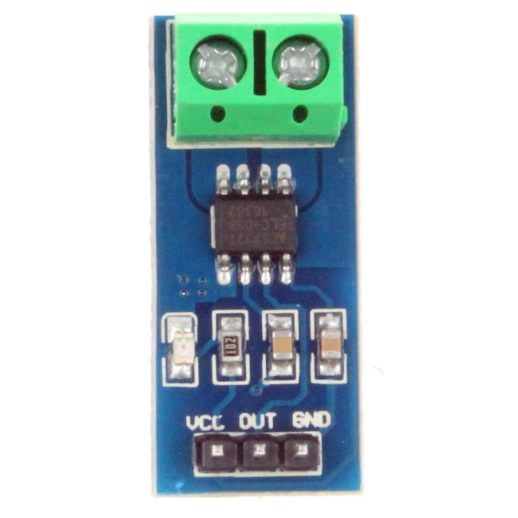
The ACS712-30A is a Hall effect-based linear current sensor designed to measure both AC and DC currents up to ±30A. It outputs an analog voltage proportional to the current flowing through it, allowing for precise current monitoring. The sensor is compact, easy to use, and widely employed in applications requiring current measurement and control.
Explore Projects Built with Sensor Arus (ACS712-30A)


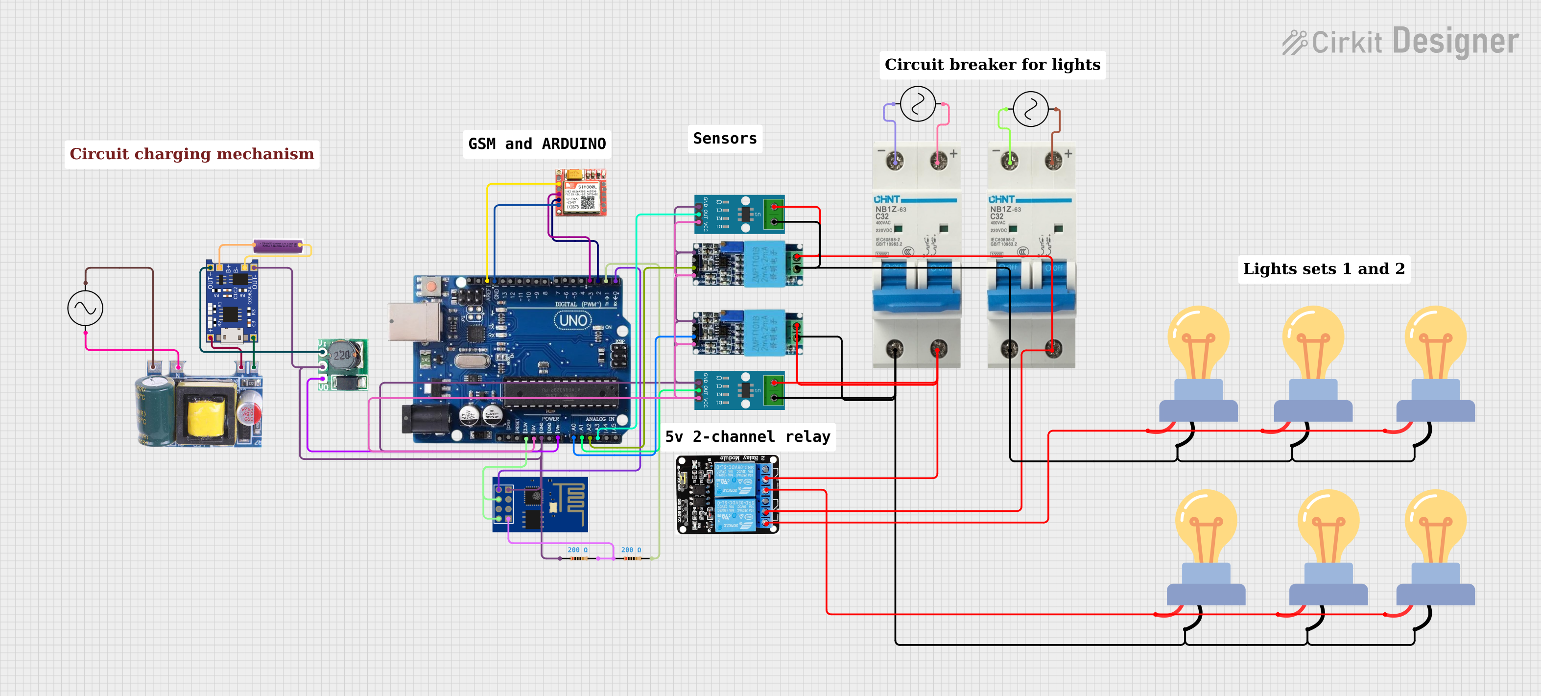

Explore Projects Built with Sensor Arus (ACS712-30A)
Common Applications
- Power monitoring in household and industrial devices
- Overcurrent protection in circuits
- Battery management systems
- Motor control and monitoring
- Energy metering in renewable energy systems
Technical Specifications
The ACS712-30A sensor is built for high accuracy and reliability. Below are its key technical details:
| Parameter | Value |
|---|---|
| Supply Voltage (Vcc) | 4.5V to 5.5V |
| Current Measurement Range | ±30A |
| Sensitivity | 66mV/A |
| Output Voltage Range | 0.5V to 4.5V |
| Zero Current Output | ~2.5V |
| Response Time | 5 µs |
| Bandwidth | 80 kHz |
| Operating Temperature | -40°C to 85°C |
| Dimensions | 27mm x 11mm x 13mm |
Pin Configuration and Descriptions
The ACS712-30A module typically has three pins for interfacing:
| Pin | Name | Description |
|---|---|---|
| 1 | Vcc | Power supply input (4.5V to 5.5V) |
| 2 | Out | Analog voltage output proportional to the current |
| 3 | GND | Ground connection |
Usage Instructions
How to Use the ACS712-30A in a Circuit
- Power the Sensor: Connect the
Vccpin to a 5V power supply and theGNDpin to the ground. - Connect the Load: Pass the current-carrying wire through the sensor's onboard Hall effect sensing loop.
- Read the Output: Measure the voltage at the
Outpin using an analog-to-digital converter (ADC) or a multimeter. The output voltage will vary linearly with the current.
Important Considerations
- Calibration: The sensor's output at zero current is approximately 2.5V. Ensure proper calibration in your circuit or software to account for this offset.
- Noise Filtering: Add a capacitor (e.g., 0.1µF) between the
Outpin andGNDto reduce noise in the output signal. - Current Direction: Positive and negative currents are indicated by output voltages above and below 2.5V, respectively.
- Avoid Overcurrent: Do not exceed the ±30A current rating to prevent damage to the sensor.
Example: Using ACS712-30A with Arduino UNO
Below is an example code to read current using the ACS712-30A sensor with an Arduino UNO:
// Define the analog pin connected to the ACS712 output
const int sensorPin = A0;

// Sensitivity of the ACS712-30A (66mV per Ampere)
const float sensitivity = 0.066; // in volts per ampere

// Zero current output voltage (approximately 2.5V)
const float zeroCurrentVoltage = 2.5; // in volts

void setup() {
  Serial.begin(9600); // Initialize serial communication
}

void loop() {
  // Read the raw analog value from the sensor
  int rawValue = analogRead(sensorPin);

  // Convert the raw value to voltage (assuming 5V reference)
  float voltage = (rawValue / 1023.0) * 5.0;

  // Calculate the current in Amperes
  float current = (voltage - zeroCurrentVoltage) / sensitivity;

  // Print the current to the Serial Monitor
  Serial.print("Current: ");
  Serial.print(current);
  Serial.println(" A");

  delay(1000); // Wait for 1 second before the next reading
}
Notes:
- Ensure the Arduino's
A0pin is connected to theOutpin of the ACS712-30A. - Use a stable 5V power supply for accurate readings.
- Adjust the
zeroCurrentVoltagevalue if the sensor's zero-current output deviates from 2.5V.
Troubleshooting and FAQs
Common Issues and Solutions
Inaccurate Readings:
- Cause: Improper calibration or noisy output.
- Solution: Calibrate the sensor by measuring the zero-current output voltage and adjust the software accordingly. Add a capacitor (e.g., 0.1µF) between the
Outpin andGNDto filter noise.
Output Voltage Stuck at 2.5V:
- Cause: No current is flowing through the sensor.
- Solution: Verify that the current-carrying wire is properly passed through the sensor's loop.
Sensor Overheating:
- Cause: Current exceeds the ±30A limit.
- Solution: Ensure the current through the sensor does not exceed its rated range.
Fluctuating Output:
- Cause: Electrical noise or unstable power supply.
- Solution: Use a decoupling capacitor on the power supply and ensure a stable 5V input.
FAQs
Q1: Can the ACS712-30A measure both AC and DC currents?
Yes, the ACS712-30A can measure both AC and DC currents within the ±30A range.
Q2: What is the resolution of the sensor?
The resolution depends on the ADC used. For example, with a 10-bit ADC (e.g., Arduino UNO), the resolution is approximately 0.029A per step.
Q3: How do I protect the sensor from overcurrent?
Use a fuse or circuit breaker rated for 30A to protect the sensor from overcurrent conditions.
Q4: Can I use the ACS712-30A with a 3.3V microcontroller?
Yes, but ensure the Out pin voltage does not exceed the ADC input range of the microcontroller. Use a voltage divider if necessary.
Q5: What is the bandwidth of the ACS712-30A?
The sensor has a bandwidth of 80 kHz, making it suitable for high-frequency current measurements.