
How to Use Triple Axis Magnetometer - HMC5883L Breakout: Examples, Pinouts, and Specs
 Design with Triple Axis Magnetometer - HMC5883L Breakout in Cirkit Designer
Introduction
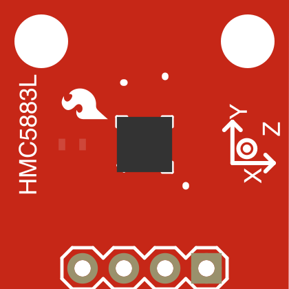
The Triple Axis Magnetometer - HMC5883L Breakout (Manufacturer Part ID: SEN-10530) is a compact and versatile sensor designed to measure magnetic fields in three dimensions (X, Y, and Z axes). Manufactured by SparkFun Electronics, this sensor is widely used in navigation, orientation, and motion-tracking applications. It provides precise digital output via the I2C interface, making it easy to integrate into microcontroller-based systems.
Common applications include:
- Electronic compasses for navigation
- Orientation sensing in robotics and drones
- Magnetic field mapping
- Augmented reality systems in smartphones
Explore Projects Built with Triple Axis Magnetometer - HMC5883L Breakout
 Open Project in Cirkit Designer
 Open Project in Cirkit Designer
 Open Project in Cirkit Designer
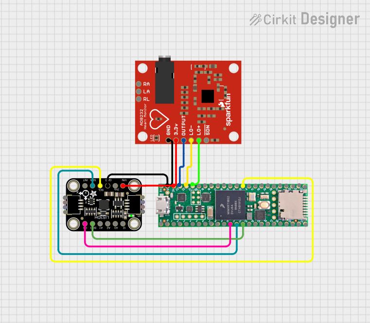 Open Project in Cirkit Designer
Explore Projects Built with Triple Axis Magnetometer - HMC5883L Breakout
Open Project in Cirkit DesignerOpen Project in Cirkit DesignerOpen Project in Cirkit DesignerOpen Project in Cirkit DesignerTechnical Specifications
The HMC5883L Breakout is built around the HMC5883L magnetometer IC, offering high sensitivity and low power consumption. Below are the key technical details:
Key Specifications
| Parameter | Value |
|---|---|
| Supply Voltage | 3.3V to 5V |
| Operating Current | 100 µA (typical) |
| Measurement Range | ±1.3 to ±8 Gauss (configurable) |
| Resolution | 12-bit ADC |
| Communication Interface | I2C (7-bit address: 0x1E) |
| Operating Temperature | -40°C to +85°C |
| Dimensions | 20.3mm x 20.3mm |
Pin Configuration
The breakout board has 4 pins for easy interfacing. Below is the pinout description:
| Pin Name | Description |
|---|---|
| VCC | Power supply input (3.3V or 5V) |
| GND | Ground |
| SDA | I2C data line |
| SCL | I2C clock line |
Usage Instructions
Connecting the HMC5883L to a Microcontroller
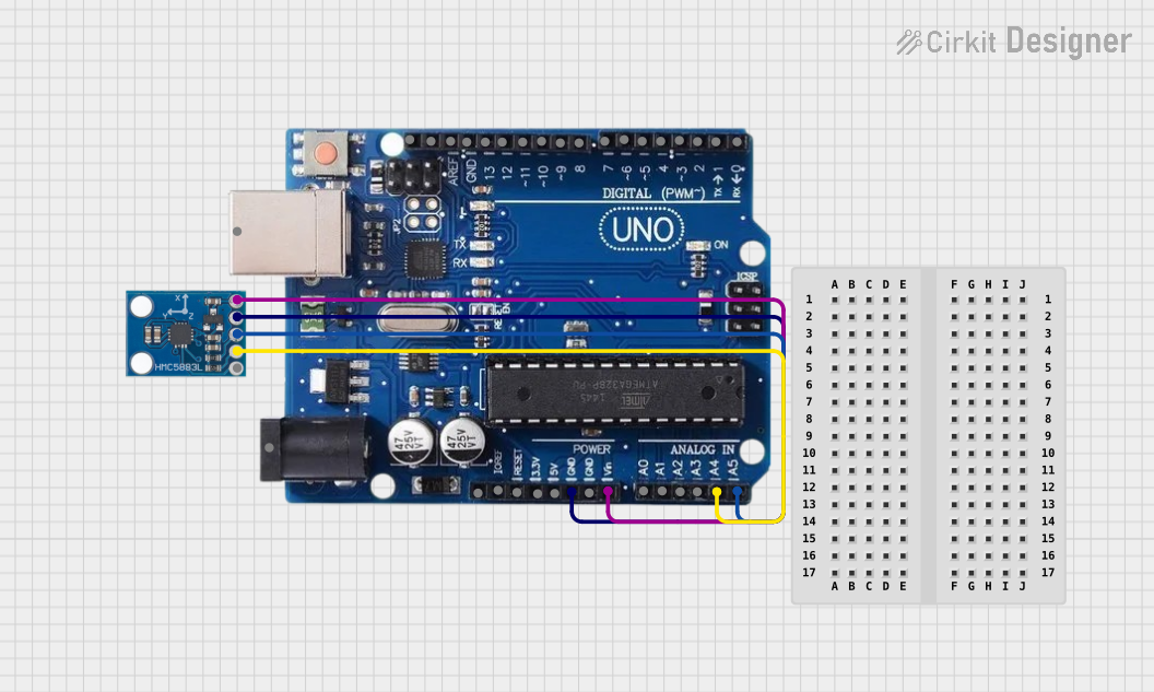
To use the HMC5883L with a microcontroller like the Arduino UNO, follow these steps:
- Connect the VCC pin to the 3.3V or 5V pin on the Arduino.
- Connect the GND pin to the Arduino's ground.
- Connect the SDA pin to the Arduino's A4 pin (I2C data line).
- Connect the SCL pin to the Arduino's A5 pin (I2C clock line).
Arduino Code Example
Below is an example Arduino sketch to read data from the HMC5883L and display it on the Serial Monitor:
#include <Wire.h>

// HMC5883L I2C address
#define HMC5883L_ADDRESS 0x1E

void setup() {
  Wire.begin(); // Initialize I2C communication
  Serial.begin(9600); // Start serial communication

  // Initialize HMC5883L
  Wire.beginTransmission(HMC5883L_ADDRESS);
  Wire.write(0x00); // Select configuration register A
  Wire.write(0x70); // Set 8-average, 15 Hz default, normal measurement
  Wire.endTransmission();

  Wire.beginTransmission(HMC5883L_ADDRESS);
  Wire.write(0x01); // Select configuration register B
  Wire.write(0x20); // Set gain to 1.3 Gauss
  Wire.endTransmission();

  Wire.beginTransmission(HMC5883L_ADDRESS);
  Wire.write(0x02); // Select mode register
  Wire.write(0x00); // Continuous measurement mode
  Wire.endTransmission();
}

void loop() {
  int16_t x, y, z;

  // Request 6 bytes of data from the HMC5883L
  Wire.beginTransmission(HMC5883L_ADDRESS);
  Wire.write(0x03); // Start reading from data output register
  Wire.endTransmission();
  Wire.requestFrom(HMC5883L_ADDRESS, 6);

  if (Wire.available() == 6) {
    x = (Wire.read() << 8) | Wire.read(); // Combine MSB and LSB for X-axis
    z = (Wire.read() << 8) | Wire.read(); // Combine MSB and LSB for Z-axis
    y = (Wire.read() << 8) | Wire.read(); // Combine MSB and LSB for Y-axis
  }

  // Print the magnetic field values
  Serial.print("X: ");
  Serial.print(x);
  Serial.print(" Y: ");
  Serial.print(y);
  Serial.print(" Z: ");
  Serial.println(z);

  delay(500); // Wait for 500ms before the next reading
}
Important Considerations
- Ensure pull-up resistors (typically 4.7kΩ) are connected to the SDA and SCL lines if not already present on the breakout board.
- Avoid placing the sensor near ferromagnetic materials or strong magnetic fields, as they can interfere with measurements.
- Calibrate the sensor for accurate readings, especially if used in a new environment.
Troubleshooting and FAQs
Common Issues
No data or incorrect readings:
- Verify the wiring connections, especially the SDA and SCL lines.
- Ensure the I2C address (0x1E) matches the one in your code.
Fluctuating or unstable readings:
- Check for nearby sources of electromagnetic interference.
- Ensure the power supply is stable and within the specified range.
Sensor not detected:
- Use an I2C scanner sketch to confirm the sensor's address.
- Ensure pull-up resistors are present on the I2C lines.
FAQs
Q: Can the HMC5883L measure absolute orientation?
A: No, the HMC5883L only measures magnetic field strength along the X, Y, and Z axes. To determine absolute orientation, combine it with an accelerometer and gyroscope.
Q: Is the HMC5883L compatible with 3.3V systems?
A: Yes, the breakout board supports both 3.3V and 5V logic levels.
Q: How do I calibrate the HMC5883L?
A: Rotate the sensor in all directions to collect raw data, then use software algorithms to calculate offsets and scale factors for each axis.
By following this documentation, you can effectively integrate the HMC5883L into your projects for accurate magnetic field measurements.