How to Use predictive sensor: Examples, Pinouts, and Specs
Introduction
A predictive sensor is a sophisticated electronic device that leverages data analysis and algorithms to anticipate future events or conditions. By analyzing patterns and trends in real-time or historical data, predictive sensors provide actionable insights, enabling systems to make informed decisions proactively. These sensors are widely used in automation, smart systems, and industrial applications to enhance efficiency, reduce downtime, and improve overall system performance.
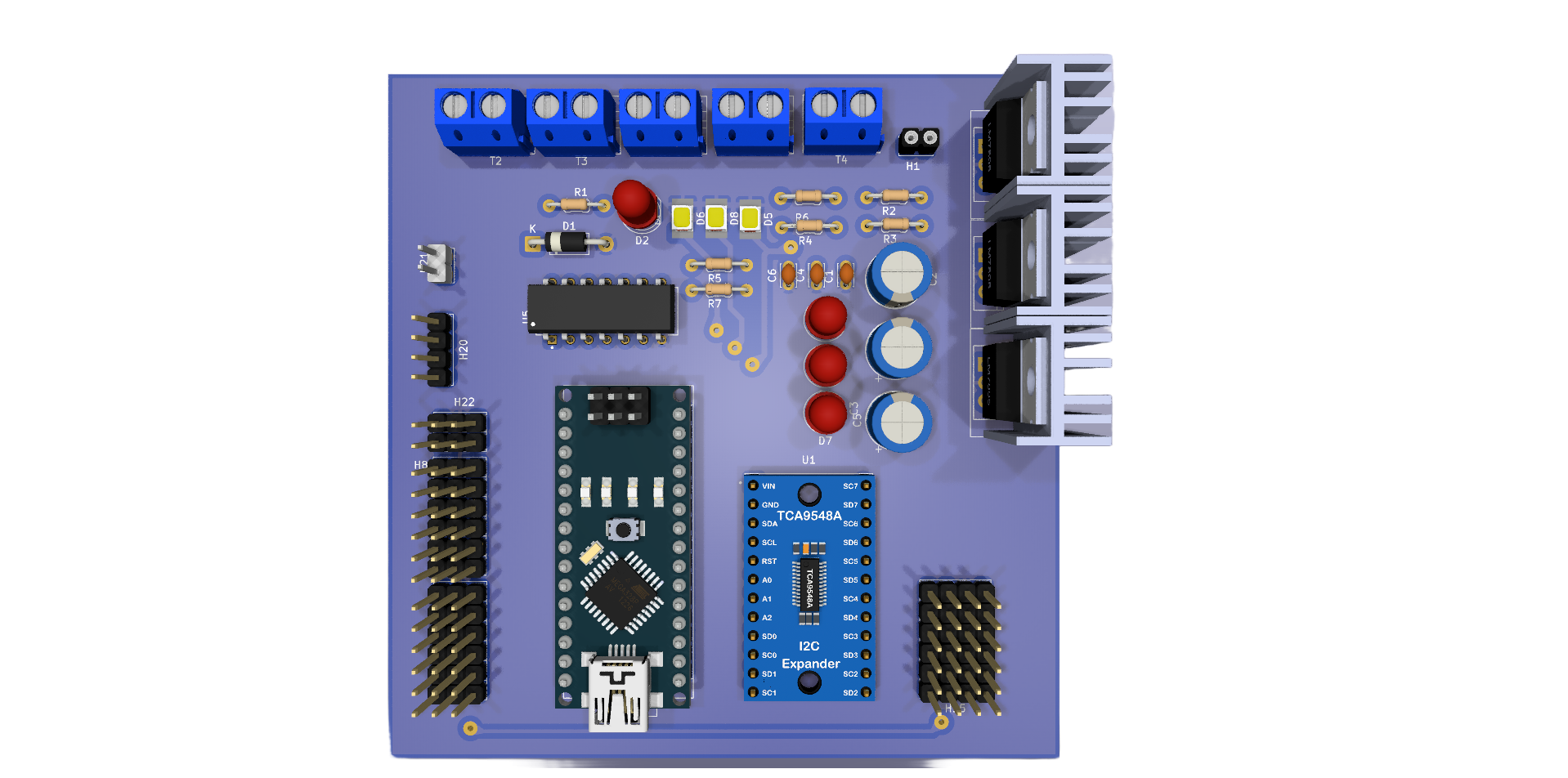
Explore Projects Built with predictive sensor
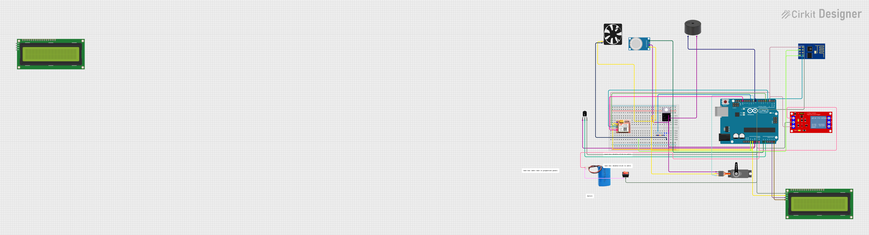
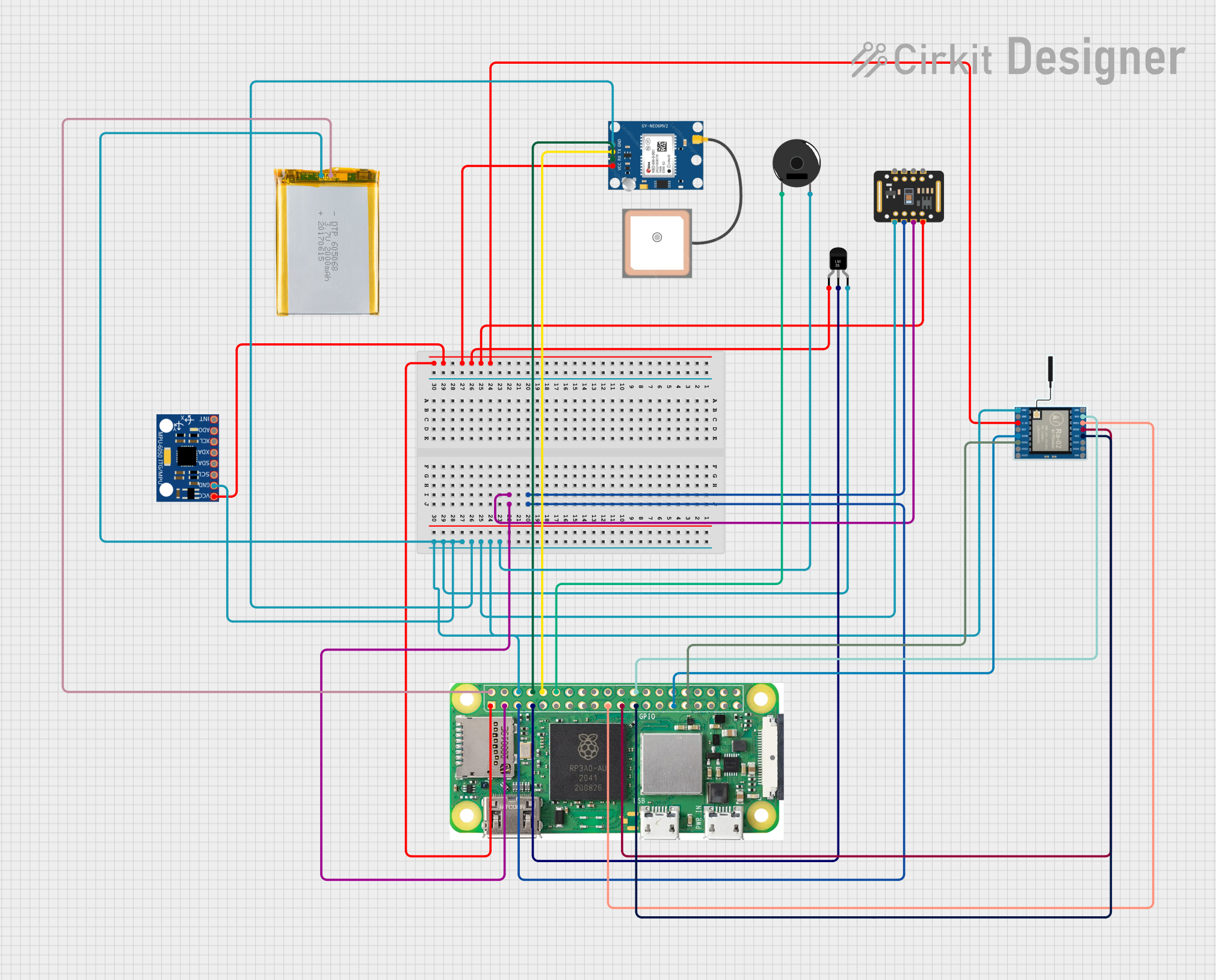

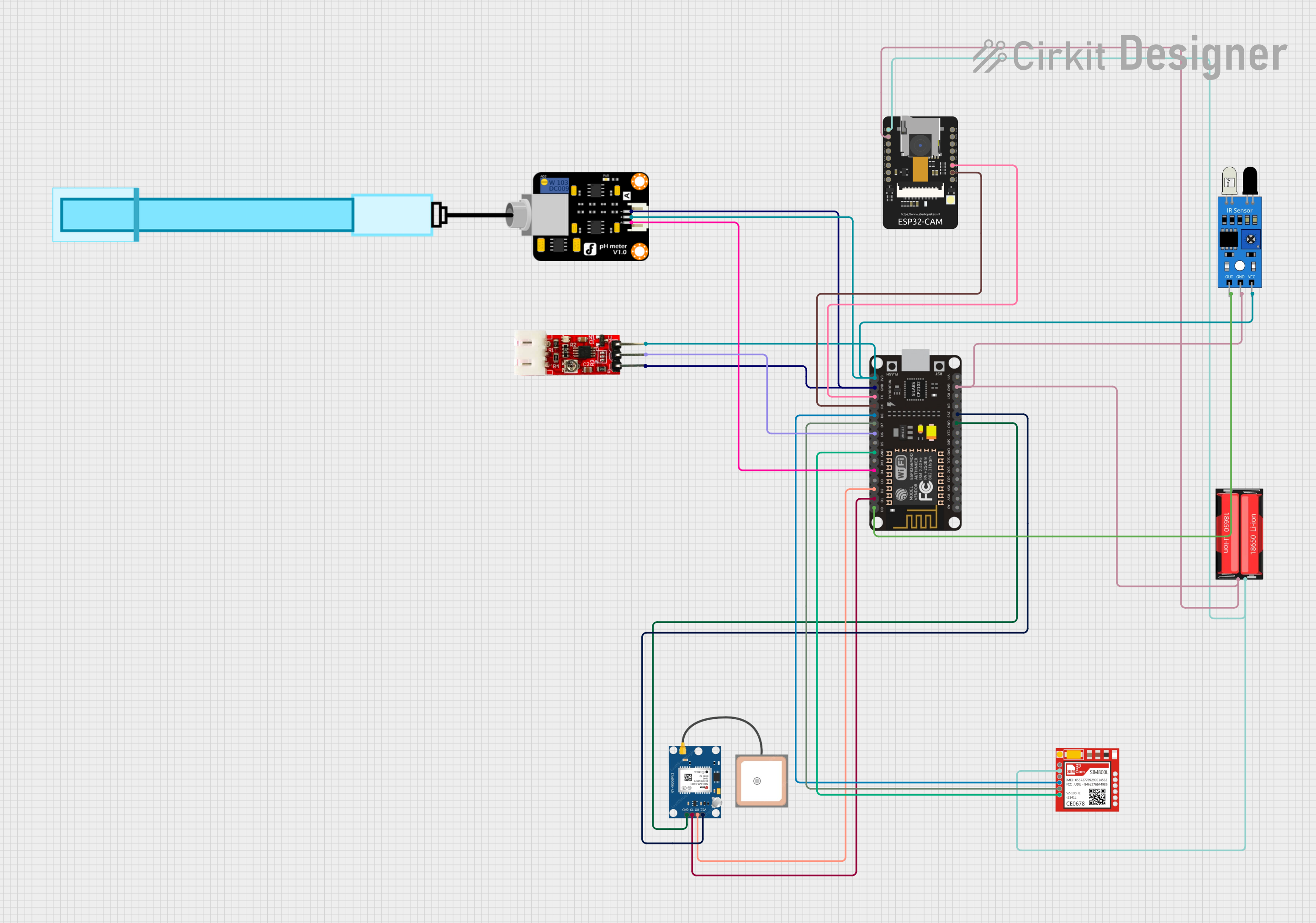
Explore Projects Built with predictive sensor
Common Applications and Use Cases
- Industrial Automation: Predictive maintenance of machinery by identifying potential failures.
- Smart Homes: Optimizing energy usage and improving home security.
- Healthcare: Monitoring patient data to predict health conditions.
- Transportation: Anticipating traffic patterns and vehicle maintenance needs.
- Agriculture: Forecasting weather conditions and soil health for better crop management.
Technical Specifications
Below are the general technical specifications for a predictive sensor. Note that specific models may vary slightly in their parameters.
Key Technical Details
- Operating Voltage: 3.3V to 5V DC
- Current Consumption: 10mA to 50mA (depending on processing load)
- Communication Protocols: I2C, SPI, UART
- Operating Temperature: -20°C to 85°C
- Data Processing Capability: Real-time analysis with onboard microcontroller
- Output: Digital signal or processed data via communication interface
- Sampling Rate: Up to 1 kHz (model-dependent)
Pin Configuration and Descriptions
The pinout for a typical predictive sensor module is as follows:
| Pin | Name | Description |
|---|---|---|
| 1 | VCC | Power supply input (3.3V to 5V DC). |
| 2 | GND | Ground connection. |
| 3 | SDA | Data line for I2C communication. |
| 4 | SCL | Clock line for I2C communication. |
| 5 | TX | Transmit pin for UART communication. |
| 6 | RX | Receive pin for UART communication. |
| 7 | INT | Interrupt pin for signaling events or alerts. |
| 8 | NC/Custom Pin | Not connected or reserved for custom functionality (varies by manufacturer). |
Usage Instructions
How to Use the Component in a Circuit
- Power the Sensor: Connect the VCC pin to a 3.3V or 5V power source and the GND pin to the ground.
- Choose a Communication Protocol:
- For I2C: Connect the SDA and SCL pins to the corresponding pins on your microcontroller.
- For UART: Connect the TX and RX pins to the UART pins on your microcontroller.
- Interrupt Pin (Optional): Use the INT pin to receive alerts or event notifications from the sensor.
- Data Processing: Use the microcontroller to read and process the data output by the sensor.
Important Considerations and Best Practices
- Power Supply: Ensure the power supply voltage matches the sensor's requirements to avoid damage.
- Communication Protocol: Configure the microcontroller to use the correct protocol (I2C, SPI, or UART) and settings.
- Data Filtering: Implement filtering algorithms in your microcontroller code to handle noisy or incomplete data.
- Calibration: Some predictive sensors may require calibration before use for accurate predictions.
- Environmental Conditions: Avoid exposing the sensor to extreme temperatures or humidity beyond its operating range.
Example Code for Arduino UNO
Below is an example of how to interface a predictive sensor with an Arduino UNO using the I2C protocol:
#include <Wire.h> // Include the Wire library for I2C communication

#define SENSOR_ADDRESS 0x40 // Replace with the sensor's I2C address

void setup() {
  Wire.begin(); // Initialize I2C communication
  Serial.begin(9600); // Start serial communication for debugging

  // Send initialization command to the sensor
  Wire.beginTransmission(SENSOR_ADDRESS);
  Wire.write(0x01); // Example command to initialize the sensor
  Wire.endTransmission();

  Serial.println("Predictive sensor initialized.");
}

void loop() {
  Wire.beginTransmission(SENSOR_ADDRESS);
  Wire.write(0x02); // Example command to request data
  Wire.endTransmission();

  Wire.requestFrom(SENSOR_ADDRESS, 2); // Request 2 bytes of data
  if (Wire.available() == 2) {
    int highByte = Wire.read(); // Read the high byte
    int lowByte = Wire.read();  // Read the low byte
    int sensorData = (highByte << 8) | lowByte; // Combine bytes into a single value

    Serial.print("Sensor Data: ");
    Serial.println(sensorData); // Print the sensor data
  }

  delay(1000); // Wait 1 second before the next reading
}
Troubleshooting and FAQs
Common Issues and Solutions
No Data Output:
- Cause: Incorrect wiring or communication protocol settings.
- Solution: Double-check the connections and ensure the microcontroller is configured for the correct protocol.
Inaccurate Predictions:
- Cause: Sensor not calibrated or exposed to environmental interference.
- Solution: Perform calibration as per the manufacturer's instructions and ensure the sensor is used within its specified operating conditions.
Sensor Not Responding:
- Cause: Power supply issues or incorrect I2C address.
- Solution: Verify the power supply voltage and check the sensor's datasheet for the correct I2C address.
Intermittent Data Loss:
- Cause: Noisy communication lines or insufficient pull-up resistors for I2C.
- Solution: Add appropriate pull-up resistors (typically 4.7kΩ) to the SDA and SCL lines.
FAQs
Q: Can the predictive sensor work with 3.3V microcontrollers?
- A: Yes, most predictive sensors are compatible with both 3.3V and 5V systems. Check the datasheet for confirmation.
Q: How do I know if the sensor needs calibration?
- A: Refer to the manufacturer's documentation. Some sensors include a self-calibration feature, while others require manual calibration.
Q: Can I use multiple predictive sensors on the same I2C bus?
- A: Yes, as long as each sensor has a unique I2C address. Some sensors allow address configuration via jumpers or software.
Q: What is the typical lifespan of a predictive sensor?
- A: The lifespan depends on the operating environment and usage, but most sensors are designed for long-term reliability in industrial applications.