
How to Use QFN-28: Examples, Pinouts, and Specs
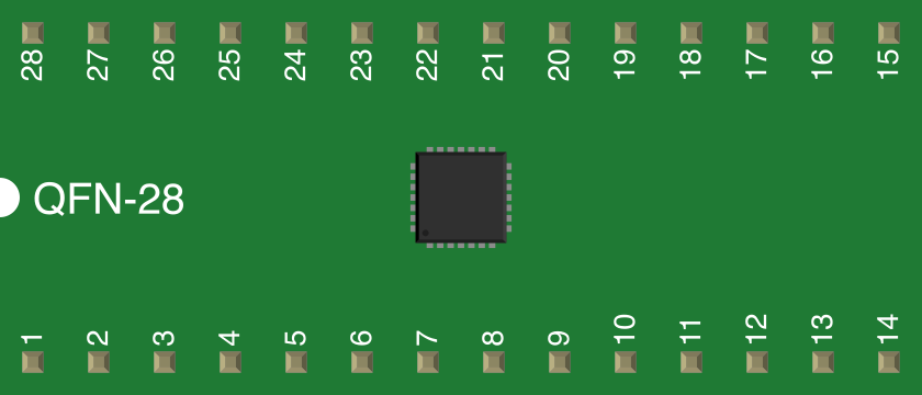
 Design with QFN-28 in Cirkit Designer
Introduction
The QFN-28 (Quad Flat No-lead) package is a surface-mount integrated circuit package with 28 pins. It is designed to provide a compact, lightweight, and thermally efficient solution for modern electronic devices. The QFN-28 package is widely used in applications requiring high-frequency performance, low inductance, and excellent thermal dissipation. Its leadless design ensures minimal parasitic effects, making it ideal for RF circuits, microcontrollers, and power management ICs.
Explore Projects Built with QFN-28
 Open Project in Cirkit Designer
 Open Project in Cirkit Designer
 Open Project in Cirkit Designer
 Open Project in Cirkit Designer
Explore Projects Built with QFN-28
Open Project in Cirkit DesignerOpen Project in Cirkit DesignerOpen Project in Cirkit DesignerOpen Project in Cirkit DesignerCommon Applications
- RF and microwave circuits
- Microcontrollers and digital signal processors (DSPs)
- Power management ICs
- High-speed communication devices
- Consumer electronics (e.g., smartphones, tablets, and wearables)
Technical Specifications
Key Technical Details
| Parameter | Value |
|---|---|
| Package Type | Quad Flat No-lead (QFN) |
| Pin Count | 28 |
| Dimensions | Typically 5 mm x 5 mm (varies by manufacturer) |
| Lead Pitch | 0.5 mm |
| Mounting Type | Surface Mount Technology (SMT) |
| Thermal Resistance (Junction to Case) | ~10-20 °C/W (varies by design) |
| Operating Temperature | -40 °C to +125 °C |
| Electrical Performance | Low inductance, suitable for high-frequency applications |
Pin Configuration and Descriptions
The QFN-28 package typically features 28 pins arranged symmetrically around the package. The exact pinout depends on the specific IC housed in the QFN-28 package. Below is a generic example of a QFN-28 pin configuration:
| Pin Number | Pin Name | Description |
|---|---|---|
| 1 | VDD | Power supply input |
| 2-7 | GPIO/IO | General-purpose input/output pins |
| 8 | GND | Ground |
| 9-14 | Analog IN/OUT | Analog input/output pins |
| 15 | RESET | Reset pin |
| 16-21 | SPI/I2C | Communication interface pins |
| 22-27 | PWM/Timer | Pulse-width modulation or timer pins |
| 28 | NC or GND | No connection or additional ground pin |
Note: Always refer to the datasheet of the specific IC in the QFN-28 package for the exact pinout and functionality.
Usage Instructions
How to Use the QFN-28 in a Circuit
PCB Design:
- Ensure the PCB layout includes a thermal pad under the QFN-28 package for heat dissipation.
- Use vias to connect the thermal pad to a ground plane for optimal thermal performance.
- Maintain proper spacing between pins to avoid solder bridging.
Soldering:
- Use reflow soldering for mounting the QFN-28 package onto the PCB.
- Apply solder paste evenly on the PCB pads, including the thermal pad.
- Follow the recommended reflow temperature profile provided by the IC manufacturer.
Testing and Debugging:
- Use test points on the PCB for critical signals to facilitate debugging.
- Verify the solder joints under the QFN-28 package using X-ray inspection if available.
Important Considerations and Best Practices
- Thermal Management: Always ensure proper thermal dissipation by connecting the thermal pad to a ground plane with multiple vias.
- Signal Integrity: Minimize trace lengths for high-frequency signals to reduce parasitic inductance and capacitance.
- Moisture Sensitivity: QFN packages are moisture-sensitive. Store them in a dry environment and follow the manufacturer's guidelines for handling and baking if necessary.
Example: Connecting a QFN-28 Microcontroller to an Arduino UNO
If the QFN-28 package houses a microcontroller, you can interface it with an Arduino UNO using SPI or I2C communication. Below is an example of Arduino code for SPI communication:
#include <SPI.h>

// Define SPI pins for the QFN-28 microcontroller
const int CS_PIN = 10; // Chip Select pin
const int MOSI_PIN = 11; // Master Out Slave In
const int MISO_PIN = 12; // Master In Slave Out
const int SCK_PIN = 13; // Serial Clock

void setup() {
  // Initialize SPI communication
  SPI.begin();

  // Set Chip Select pin as output
  pinMode(CS_PIN, OUTPUT);

  // Set Chip Select high to deselect the device
  digitalWrite(CS_PIN, HIGH);

  Serial.begin(9600); // Initialize serial communication for debugging
}

void loop() {
  // Example: Send data to the QFN-28 microcontroller
  digitalWrite(CS_PIN, LOW); // Select the device
  SPI.transfer(0x55); // Send a byte of data (example: 0x55)
  digitalWrite(CS_PIN, HIGH); // Deselect the device

  delay(1000); // Wait for 1 second
}
Note: Modify the pin definitions and SPI settings as per the specific QFN-28 microcontroller's datasheet.
Troubleshooting and FAQs
Common Issues
Soldering Defects:
- Issue: Poor solder joints or solder bridging between pins.
- Solution: Use a stencil for precise solder paste application and inspect solder joints under a microscope or X-ray.
Thermal Issues:
- Issue: Overheating due to insufficient thermal dissipation.
- Solution: Ensure the thermal pad is properly connected to a ground plane with adequate vias.
Signal Integrity Problems:
- Issue: Noise or signal distortion in high-frequency circuits.
- Solution: Use proper PCB design techniques, such as controlled impedance traces and decoupling capacitors.
Moisture Sensitivity:
- Issue: Package damage due to moisture absorption during soldering.
- Solution: Store QFN-28 packages in a dry environment and bake them if required before soldering.
FAQs
Q1: Can I hand-solder a QFN-28 package?
A1: Hand-soldering a QFN-28 package is challenging due to its leadless design. It is recommended to use reflow soldering for reliable results.
Q2: How do I inspect solder joints under a QFN-28 package?
A2: Use X-ray inspection to verify solder joints, as the leads are not visible from the sides.
Q3: What is the purpose of the thermal pad?
A3: The thermal pad improves heat dissipation and reduces the risk of overheating. It should be connected to a ground plane with multiple vias.
Q4: Can I use a QFN-28 package for high-frequency applications?
A4: Yes, the QFN-28 package is well-suited for high-frequency applications due to its low inductance and minimal parasitic effects.