
How to Use magnetic contactor: Examples, Pinouts, and Specs
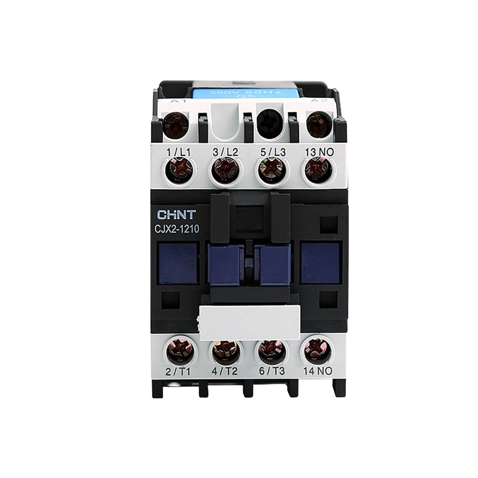
 Design with magnetic contactor in Cirkit Designer
Introduction
A magnetic contactor is an electrically controlled switch used for switching power circuits. It operates similarly to a relay but is specifically designed to handle higher current applications. The core of the magnetic contactor consists of an electromagnet that, when energized, pulls a set of contacts together to close the circuit. Magnetic contactors are widely used in industrial and commercial applications for controlling electric motors, lighting systems, heating equipment, and other high-power devices.
Explore Projects Built with magnetic contactor
 Open Project in Cirkit Designer
 Open Project in Cirkit Designer
 Open Project in Cirkit Designer
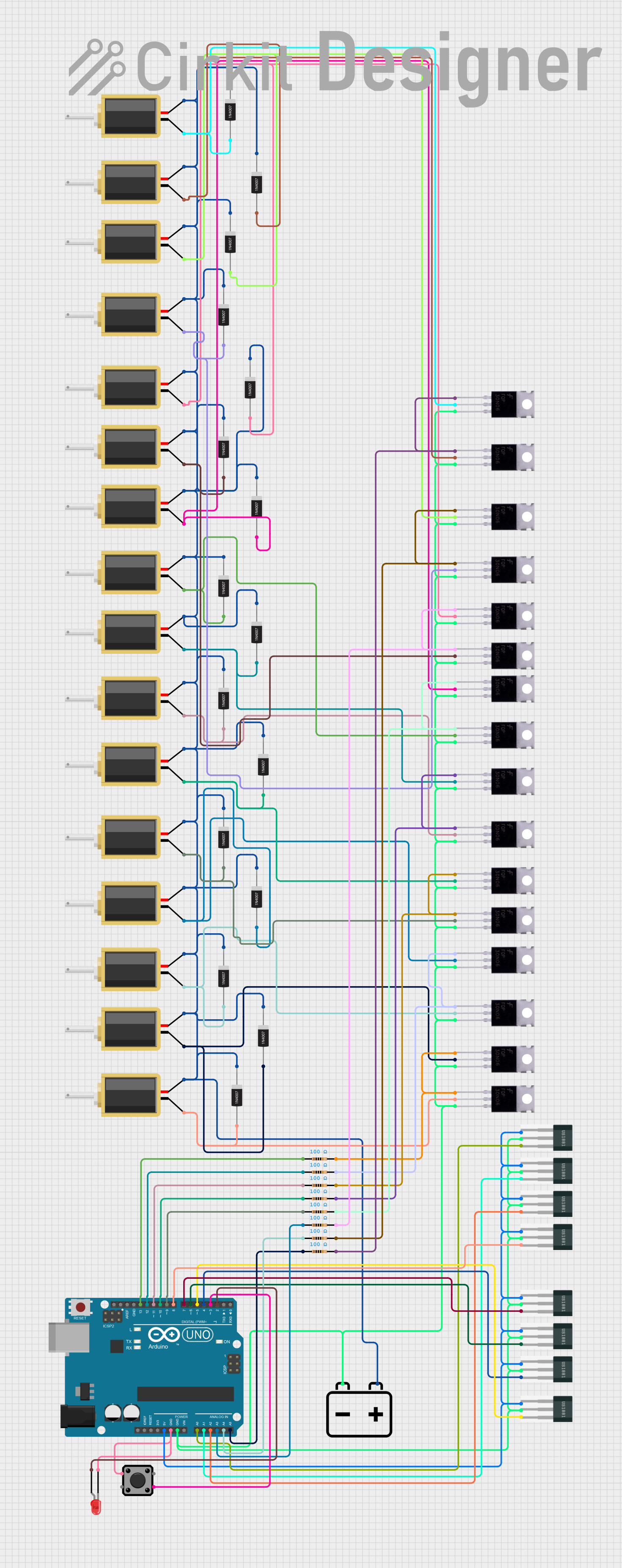 Open Project in Cirkit Designer
Explore Projects Built with magnetic contactor
Open Project in Cirkit DesignerOpen Project in Cirkit DesignerOpen Project in Cirkit DesignerOpen Project in Cirkit DesignerCommon Applications and Use Cases
- Electric Motor Control: Starting, stopping, and reversing motors in industrial machinery.
- Lighting Systems: Controlling large lighting loads in commercial buildings.
- Heating Systems: Switching high-power heating elements in HVAC systems.
- Power Distribution: Managing power circuits in industrial automation systems.
Technical Specifications
Below are the key technical details of a typical magnetic contactor. Specifications may vary depending on the model and manufacturer.
General Specifications
- Rated Voltage: 24V, 110V, 220V, or 440V AC/DC (depending on the coil type)
- Rated Current: 9A to 800A (varies by model)
- Contact Configuration: 3-pole (3-phase) or 4-pole
- Coil Power Consumption: Typically 3-10W
- Mechanical Life: Up to 10 million operations
- Electrical Life: Up to 1 million operations (depending on load)
Pin Configuration and Descriptions
The magnetic contactor typically has the following terminals:
| Pin/Terminal | Description |
|---|---|
| L1, L2, L3 | Input terminals for the three-phase power supply (main circuit). |
| T1, T2, T3 | Output terminals connected to the load (e.g., motor, lighting system). |
| A1, A2 | Coil terminals for energizing the electromagnet (control circuit). |
| NO (Normally Open) | Auxiliary contact for additional control or signaling when the contactor is ON. |
| NC (Normally Closed) | Auxiliary contact for additional control or signaling when the contactor is OFF. |
Usage Instructions
How to Use the Magnetic Contactor in a Circuit
- Determine the Load Requirements: Identify the voltage, current, and power ratings of the load (e.g., motor or lighting system) to select a suitable contactor.
- Connect the Main Circuit:
- Connect the three-phase power supply to the input terminals (L1, L2, L3).
- Connect the load (e.g., motor) to the output terminals (T1, T2, T3).
- Connect the Control Circuit:
- Connect the control voltage source (e.g., 24V DC or 220V AC) to the coil terminals (A1, A2).
- Optionally, include a push-button switch or relay in series with the coil for manual or automated control.
- Use Auxiliary Contacts:
- Use the NO or NC auxiliary contacts for additional control logic or signaling (e.g., to indicate the contactor's state).
- Test the Circuit:
- Energize the control circuit to activate the contactor and verify that the load operates as expected.
Important Considerations and Best Practices
- Overload Protection: Always use an overload relay or circuit breaker in series with the contactor to protect the load and wiring.
- Voltage Compatibility: Ensure the coil voltage matches the control circuit voltage.
- Proper Mounting: Mount the contactor securely on a DIN rail or panel to prevent vibration-related issues.
- Avoid Overheating: Ensure adequate ventilation around the contactor to prevent overheating during operation.
- Regular Maintenance: Periodically inspect the contactor for wear, dirt, or loose connections.
Example: Connecting a Magnetic Contactor to an Arduino UNO
You can use an Arduino UNO to control a magnetic contactor via a relay module. Below is an example code snippet:
// Magnetic Contactor Control with Arduino UNO
// This code uses a relay module to control the contactor's coil.

const int relayPin = 7; // Pin connected to the relay module

void setup() {
  pinMode(relayPin, OUTPUT); // Set relay pin as output
  digitalWrite(relayPin, LOW); // Ensure relay is off at startup
}

void loop() {
  // Turn the contactor ON
  digitalWrite(relayPin, HIGH); // Activate relay to energize contactor coil
  delay(5000); // Keep the contactor ON for 5 seconds

  // Turn the contactor OFF
  digitalWrite(relayPin, LOW); // Deactivate relay to de-energize contactor coil
  delay(5000); // Keep the contactor OFF for 5 seconds
}
Note: Ensure the relay module is rated for the contactor's coil voltage and current. Use an external power supply if necessary to avoid overloading the Arduino.
Troubleshooting and FAQs
Common Issues and Solutions
Contactor Does Not Energize:
- Cause: Incorrect coil voltage or loose connections.
- Solution: Verify the control circuit voltage and ensure all connections are secure.
Contactor Buzzing Noise:
- Cause: Insufficient coil voltage or mechanical wear.
- Solution: Check the control voltage and inspect the contactor for mechanical issues.
Contacts Overheating:
- Cause: Overloaded circuit or poor contact surface.
- Solution: Ensure the load does not exceed the contactor's rated current. Clean or replace worn contacts.
Frequent Tripping:
- Cause: Overload or short circuit in the load.
- Solution: Check the load for faults and ensure proper overload protection is installed.
FAQs
Q: Can I use a magnetic contactor for single-phase loads?
A: Yes, you can use a magnetic contactor for single-phase loads by connecting only one pair of input and output terminals (e.g., L1 and T1).Q: What is the difference between a relay and a magnetic contactor?
A: A relay is designed for low-power applications, while a magnetic contactor is built to handle high-power loads and has a more robust design.Q: How do I select the right magnetic contactor for my application?
A: Consider the load's voltage, current, and power ratings, as well as the control circuit voltage. Choose a contactor with a rated capacity higher than the load's requirements.Q: Can I use a magnetic contactor outdoors?
A: Only if it is enclosed in a weatherproof housing or rated for outdoor use.