How to Use I2 ssd1315 oled 0.96: Examples, Pinouts, and Specs
Introduction
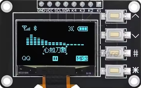
The I2C SSD1315 OLED 0.96 is a compact, low-power display module featuring a 0.96-inch OLED screen with a resolution of 128x64 pixels. It is driven by the SSD1315 controller and communicates via the I2C interface, making it an excellent choice for projects requiring a small, high-contrast display. This module is ideal for displaying text, graphics, and simple animations in embedded systems.
Explore Projects Built with I2 ssd1315 oled 0.96


Explore Projects Built with I2 ssd1315 oled 0.96
Common Applications and Use Cases
- Wearable devices and smart gadgets
- IoT dashboards and data visualization
- Portable measurement instruments
- Home automation displays
- Educational and hobbyist projects
Technical Specifications
Key Technical Details
| Parameter | Value |
|---|---|
| Display Type | OLED |
| Screen Size | 0.96 inches |
| Resolution | 128x64 pixels |
| Driver IC | SSD1315 |
| Interface | I2C (2-wire) |
| Operating Voltage | 3.3V to 5V |
| Operating Current | ~20mA |
| Viewing Angle | >160° |
| Communication Address | 0x3C (default) or 0x3D |
Pin Configuration and Descriptions
| Pin Name | Pin Number | Description |
|---|---|---|
| GND | 1 | Ground connection |
| VCC | 2 | Power supply (3.3V or 5V) |
| SCL | 3 | I2C clock line |
| SDA | 4 | I2C data line |
Usage Instructions
How to Use the Component in a Circuit
Wiring the OLED Module:
- Connect the
GNDpin of the OLED to the ground of your microcontroller. - Connect the
VCCpin to the 3.3V or 5V power supply (depending on your microcontroller). - Connect the
SCLpin to the I2C clock pin of your microcontroller (e.g., A5 on Arduino UNO). - Connect the
SDApin to the I2C data pin of your microcontroller (e.g., A4 on Arduino UNO).
- Connect the
Install Required Libraries:
- For Arduino, install the
Adafruit_GFXandAdafruit_SSD1306libraries via the Arduino Library Manager.
- For Arduino, install the
Basic Arduino Code Example: Below is an example code to display "Hello, World!" on the OLED:
// Include necessary libraries
#include <Wire.h>
#include <Adafruit_GFX.h>
#include <Adafruit_SSD1306.h>

// Define OLED display width and height
#define SCREEN_WIDTH 128
#define SCREEN_HEIGHT 64

// Create an SSD1306 display object (I2C address 0x3C)
Adafruit_SSD1306 display(SCREEN_WIDTH, SCREEN_HEIGHT, &Wire, -1);

void setup() {
  // Initialize the display
  if (!display.begin(SSD1306_I2C_ADDRESS, 0x3C)) {
    // If initialization fails, print an error message
    Serial.println(F("SSD1306 allocation failed"));
    for (;;); // Halt execution
  }

  // Clear the display buffer
  display.clearDisplay();

  // Set text size and color
  display.setTextSize(1); // Text size multiplier
  display.setTextColor(SSD1306_WHITE);

  // Set cursor position
  display.setCursor(0, 0);

  // Print text to the display buffer
  display.println(F("Hello, World!"));

  // Display the buffer content on the screen
  display.display();
}

void loop() {
  // Nothing to do here
}
Important Considerations and Best Practices
- Ensure the I2C address (default
0x3C) matches the address configured in your code. - Use pull-up resistors (typically 4.7kΩ) on the
SCLandSDAlines if your microcontroller does not have internal pull-ups. - Avoid exceeding the operating voltage range to prevent damage to the module.
- Keep the OLED away from direct sunlight to prevent screen degradation.
Troubleshooting and FAQs
Common Issues and Solutions
The display does not turn on:
- Verify the wiring connections, especially
GNDandVCC. - Ensure the power supply voltage is within the specified range (3.3V to 5V).
- Check if the I2C address in the code matches the module's address.
- Verify the wiring connections, especially
Nothing is displayed on the screen:
- Confirm that the
Adafruit_GFXandAdafruit_SSD1306libraries are installed. - Ensure the
display.begin()function is called with the correct I2C address. - Check for loose connections on the
SCLandSDAlines.
- Confirm that the
Flickering or unstable display:
- Use shorter wires to reduce noise on the I2C lines.
- Add pull-up resistors to the
SCLandSDAlines if not already present.
Text or graphics appear distorted:
- Call
display.clearDisplay()before updating the screen to avoid overlapping content. - Verify that the screen dimensions in the code match the module's resolution (128x64).
- Call
FAQs
Q: Can I use this module with a 3.3V microcontroller?
A: Yes, the module is compatible with both 3.3V and 5V systems.
Q: How do I change the I2C address?
A: The I2C address can be changed by modifying the solder jumpers on the back of the module. Refer to the module's datasheet for details.
Q: Can I display images on this OLED?
A: Yes, you can display monochrome bitmap images by converting them to the appropriate format using tools like LCD Assistant.
Q: Is this module compatible with Raspberry Pi?
A: Yes, the module works with Raspberry Pi. Use the Adafruit_SSD1306 Python library for implementation.
By following this documentation, you can effectively integrate the I2C SSD1315 OLED 0.96 into your projects for a wide range of applications.