
How to Use Rocker Switch (SPST): Examples, Pinouts, and Specs
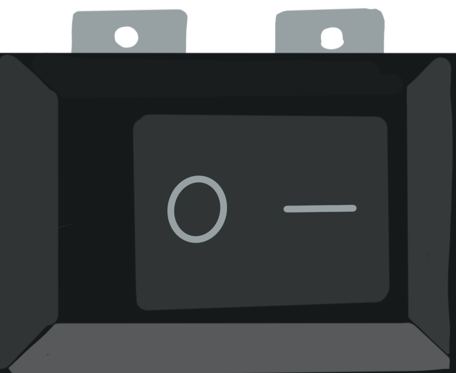
 Design with Rocker Switch (SPST) in Cirkit Designer
Introduction
A Rocker Switch (Single Pole Single Throw), manufactured by Switch Electronics, is a simple yet versatile electrical switch designed to toggle between two positions: ON and OFF. This switch allows or interrupts the flow of current in a circuit, making it ideal for controlling power to devices. Its intuitive design and reliability make it a popular choice in a wide range of applications.
Explore Projects Built with Rocker Switch (SPST)
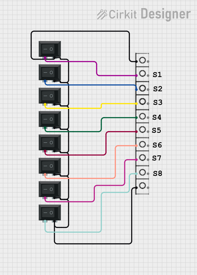 Open Project in Cirkit Designer
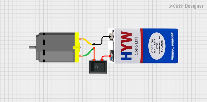 Open Project in Cirkit Designer
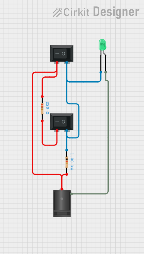 Open Project in Cirkit Designer
 Open Project in Cirkit Designer
Explore Projects Built with Rocker Switch (SPST)
Open Project in Cirkit DesignerOpen Project in Cirkit DesignerOpen Project in Cirkit DesignerOpen Project in Cirkit DesignerCommon Applications and Use Cases
- Power control for household appliances
- Automotive electronics (e.g., dashboard switches)
- Industrial equipment and machinery
- DIY electronics projects
- Lighting systems
Technical Specifications
Below are the key technical details for the Rocker Switch (SPST):
| Parameter | Value |
|---|---|
| Manufacturer | Switch Electronics |
| Manufacturer Part ID | N/A |
| Switch Type | Single Pole Single Throw (SPST) |
| Rated Voltage | 12V DC (typical), up to 250V AC |
| Rated Current | 6A @ 250V AC, 10A @ 125V AC |
| Contact Resistance | ≤ 50 mΩ |
| Insulation Resistance | ≥ 100 MΩ @ 500V DC |
| Operating Temperature | -25°C to +85°C |
| Mechanical Life | 10,000 cycles |
| Mounting Style | Panel mount |
| Actuator Type | Rocker |
Pin Configuration and Descriptions
The Rocker Switch (SPST) typically has two terminals for connection:
| Pin | Description |
|---|---|
| Pin 1 | Input terminal (connect to the power source) |
| Pin 2 | Output terminal (connect to the load or device) |
Usage Instructions
How to Use the Rocker Switch in a Circuit
- Identify the Terminals: Locate the two terminals on the switch. Pin 1 is for the input (power source), and Pin 2 is for the output (load or device).
- Prepare the Circuit:
- Ensure the circuit is powered off before making any connections.
- Use appropriate wires and connectors to handle the rated current and voltage.
- Connect the Switch:
- Connect Pin 1 to the positive terminal of the power source.
- Connect Pin 2 to the positive terminal of the load or device.
- Complete the circuit by connecting the negative terminal of the power source to the negative terminal of the load.
- Mount the Switch:
- Insert the switch into the panel cutout and secure it using the built-in clips or screws.
- Test the Circuit:
- Power on the circuit and toggle the switch to verify its operation.
Important Considerations and Best Practices
- Voltage and Current Ratings: Ensure the switch is used within its rated voltage and current limits to prevent overheating or damage.
- Debouncing: For digital circuits, consider adding a debouncing circuit or software logic to handle switch bounce.
- Safety: Always disconnect power before wiring or modifying the circuit.
- Mounting: Ensure the switch is securely mounted to prevent accidental disconnection or damage.
Example: Connecting to an Arduino UNO
The Rocker Switch (SPST) can be used with an Arduino UNO to control an LED. Below is an example circuit and code:
Circuit Connections
- Connect Pin 1 of the switch to the 5V pin on the Arduino.
- Connect Pin 2 of the switch to one terminal of a 220Ω resistor.
- Connect the other terminal of the resistor to the anode (long leg) of the LED.
- Connect the cathode (short leg) of the LED to the GND pin on the Arduino.
Arduino Code
// Define the pin connected to the switch
const int switchPin = 2; // Digital pin 2 for the switch
const int ledPin = 13;   // Built-in LED on pin 13

void setup() {
  pinMode(switchPin, INPUT); // Set the switch pin as input
  pinMode(ledPin, OUTPUT);   // Set the LED pin as output
}

void loop() {
  int switchState = digitalRead(switchPin); // Read the switch state

  if (switchState == HIGH) {
    digitalWrite(ledPin, HIGH); // Turn on the LED if switch is ON
  } else {
    digitalWrite(ledPin, LOW);  // Turn off the LED if switch is OFF
  }
}
Troubleshooting and FAQs
Common Issues and Solutions
Switch Not Working:
- Cause: Loose or incorrect wiring.
- Solution: Double-check all connections and ensure the switch terminals are properly connected.
Overheating:
- Cause: Exceeding the rated current or voltage.
- Solution: Verify that the load does not exceed the switch's specifications.
Switch Bounce in Digital Circuits:
- Cause: Mechanical contacts causing rapid on/off signals.
- Solution: Use a debouncing circuit (e.g., capacitor) or implement software debouncing in your code.
LED Not Lighting in Arduino Circuit:
- Cause: Incorrect wiring or faulty components.
- Solution: Check the connections, ensure the LED is oriented correctly, and verify the resistor value.
FAQs
Q: Can this switch handle AC and DC currents?
A: Yes, the Rocker Switch (SPST) is rated for both AC and DC currents, but ensure the voltage and current do not exceed the specified limits.
Q: Is the switch waterproof?
A: No, this switch is not waterproof. For outdoor or wet environments, use a waterproof variant.
Q: Can I use this switch to control a motor?
A: Yes, as long as the motor's current and voltage are within the switch's rated specifications.
Q: How do I mount the switch?
A: The switch is designed for panel mounting. Cut a hole in the panel according to the switch's dimensions and secure it using the built-in clips or screws.
This concludes the documentation for the Rocker Switch (SPST). For further assistance, refer to the manufacturer's guidelines or contact Switch Electronics.