Cirkit Designer Logo
Cirkit Designer
Your all-in-one circuit design IDE
Home / 
Component Documentation

How to Use TFT LCD Display ST7735S: Examples, Pinouts, and Specs

Image of TFT LCD Display ST7735S
Cirkit Designer LogoDesign with TFT LCD Display ST7735S in Cirkit Designer

Introduction

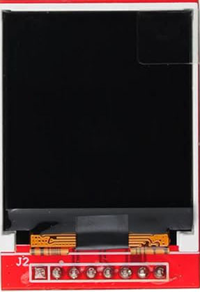
The TFT LCD Display ST7735S is a compact and versatile display module that utilizes a thin-film-transistor liquid-crystal display (TFT LCD) technology for rich color graphics. This display is controlled by the ST7735S, a single-chip controller/driver that provides a high-quality GUI interface for applications such as embedded systems, digital cameras, personal digital assistants, and mobile phones.

Explore Projects Built with TFT LCD Display ST7735S

Use Cirkit Designer to design, explore, and prototype these projects online. Some projects support real-time simulation. Click "Open Project" to start designing instantly!
ESP32-C6 and ST7735S Display: Wi-Fi Controlled TFT Display Module
Image of ESP32-C6sm-ST7735: A project utilizing TFT LCD Display ST7735S in a practical application
This circuit features an ESP32-C6 microcontroller interfaced with a China ST7735S 160x128 TFT display. The ESP32-C6 controls the display via SPI communication, providing power, ground, and control signals to render graphics and text on the screen.
Cirkit Designer LogoOpen Project in Cirkit Designer
RTL8720DN-Based Interactive Button-Controlled TFT Display
Image of coba-coba: A project utilizing TFT LCD Display ST7735S in a practical application
This circuit features an RTL8720DN microcontroller interfaced with a China ST7735S 160x128 TFT LCD display and four pushbuttons. The microcontroller reads the states of the pushbuttons and displays their statuses on the TFT LCD, providing a visual feedback system for button presses.
Cirkit Designer LogoOpen Project in Cirkit Designer
Arduino Nano-Based TFT LCD Display Interface
Image of ST7735: A project utilizing TFT LCD Display ST7735S in a practical application
This circuit interfaces an Arduino Nano with a TFT LCD Display ST7735S. The Arduino Nano controls the display by sending data and commands through its digital pins, providing power and ground connections to the display. The setup is designed for displaying information on the TFT screen, with the Arduino handling the logic and data processing.
Cirkit Designer LogoOpen Project in Cirkit Designer
Arduino Nano Controlled TFT Display with Multiple Pushbuttons
Image of rey: A project utilizing TFT LCD Display ST7735S in a practical application
This circuit features an Arduino Nano microcontroller connected to a ST7735 128x128 1.44 TFT I2C Color display and multiple pushbuttons. The display is interfaced with the Arduino via digital pins for control signals and SPI pins for data transfer. The pushbuttons are connected to various digital and analog input pins on the Arduino, likely intended for user input to control the display or other functions within the code.
Cirkit Designer LogoOpen Project in Cirkit Designer

Explore Projects Built with TFT LCD Display ST7735S

Use Cirkit Designer to design, explore, and prototype these projects online. Some projects support real-time simulation. Click "Open Project" to start designing instantly!
Image of ESP32-C6sm-ST7735: A project utilizing TFT LCD Display ST7735S in a practical application
ESP32-C6 and ST7735S Display: Wi-Fi Controlled TFT Display Module
This circuit features an ESP32-C6 microcontroller interfaced with a China ST7735S 160x128 TFT display. The ESP32-C6 controls the display via SPI communication, providing power, ground, and control signals to render graphics and text on the screen.
Cirkit Designer LogoOpen Project in Cirkit Designer
Image of coba-coba: A project utilizing TFT LCD Display ST7735S in a practical application
RTL8720DN-Based Interactive Button-Controlled TFT Display
This circuit features an RTL8720DN microcontroller interfaced with a China ST7735S 160x128 TFT LCD display and four pushbuttons. The microcontroller reads the states of the pushbuttons and displays their statuses on the TFT LCD, providing a visual feedback system for button presses.
Cirkit Designer LogoOpen Project in Cirkit Designer
Image of ST7735: A project utilizing TFT LCD Display ST7735S in a practical application
Arduino Nano-Based TFT LCD Display Interface
This circuit interfaces an Arduino Nano with a TFT LCD Display ST7735S. The Arduino Nano controls the display by sending data and commands through its digital pins, providing power and ground connections to the display. The setup is designed for displaying information on the TFT screen, with the Arduino handling the logic and data processing.
Cirkit Designer LogoOpen Project in Cirkit Designer
Image of rey: A project utilizing TFT LCD Display ST7735S in a practical application
Arduino Nano Controlled TFT Display with Multiple Pushbuttons
This circuit features an Arduino Nano microcontroller connected to a ST7735 128x128 1.44 TFT I2C Color display and multiple pushbuttons. The display is interfaced with the Arduino via digital pins for control signals and SPI pins for data transfer. The pushbuttons are connected to various digital and analog input pins on the Arduino, likely intended for user input to control the display or other functions within the code.
Cirkit Designer LogoOpen Project in Cirkit Designer

Common Applications and Use Cases

  • Embedded systems with graphical user interfaces
  • Portable instruments and meters
  • Home automation control panels
  • Wearable devices
  • DIY projects and hobbyist applications, including Arduino-based gadgets

Technical Specifications

Key Technical Details

  • Display Size: 1.44 inches
  • Resolution: 128x128 pixels
  • Color Depth: 16-bit (65K colors)
  • Interface: SPI (Serial Peripheral Interface)
  • Operating Voltage: 3.3V
  • Input Data: 8/16-bit parallel interface

Pin Configuration and Descriptions

Pin Number Pin Name Description
1 VCC Power supply (3.3V)
2 GND Ground
3 CS Chip Select, active low
4 RESET Reset signal, active low
5 A0/DC Data/Command control pin
6 SDA Serial data input
7 SCK Serial clock input
8 LED Backlight control (anode)

Usage Instructions

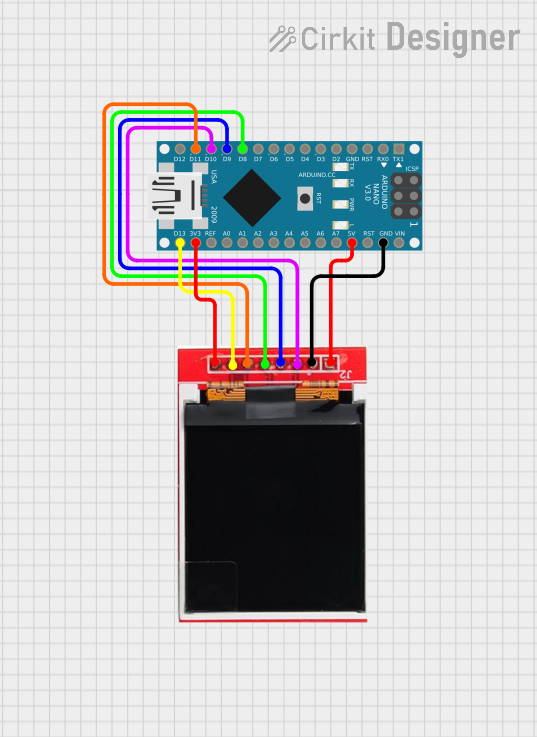
How to Use the Component in a Circuit

  1. Power Connections: Connect VCC to a 3.3V power supply and GND to the ground.
  2. Data Connections: Connect SDA to the MOSI pin and SCK to the SCK pin of your microcontroller.
  3. Control Connections: Connect CS, RESET, and A0/DC to digital I/O pins on your microcontroller.
  4. Backlight: Connect LED to a PWM-capable pin for backlight control or directly to 3.3V for constant backlight.

Important Considerations and Best Practices

  • Always ensure that the power supply is 3.3V; higher voltages can damage the display.
  • Use a level shifter if you are interfacing with a 5V microcontroller like the Arduino UNO.
  • Avoid exposing the display to direct sunlight or high temperatures to prevent damage.
  • When soldering, be cautious not to overheat the pins as it can damage the display.

Example Code for Arduino UNO

#include <Adafruit_GFX.h>    // Core graphics library
#include <Adafruit_ST7735.h> // Hardware-specific library for ST7735

#define TFT_CS     10 // Chip select line for TFT display
#define TFT_RST    9  // Reset line for TFT (or connect to +3V3)
#define TFT_DC     8  // Data/command line for TFT

// Initialize Adafruit ST7735 TFT library
Adafruit_ST7735 tft = Adafruit_ST7735(TFT_CS, TFT_DC, TFT_RST);

void setup() {
  tft.initR(INITR_144GREENTAB); // Initialize display with the correct settings
  tft.fillScreen(ST7735_BLACK);  // Clear the screen to black
}

void loop() {
  // Example: Draw a red rectangle
  tft.fillRect(10, 10, 50, 50, ST7735_RED);
  delay(500);

  // Example: Draw a text string
  tft.setCursor(0, 0);
  tft.setTextColor(ST7735_WHITE);
  tft.setTextWrap(true);
  tft.print("Hello, World!");
  delay(2000);
}

Troubleshooting and FAQs

Common Issues Users Might Face

  • Display not powering on: Check the power connections and ensure the voltage is 3.3V.
  • No display or white screen: Verify that the SPI connections are correct and the CS, RESET, and A0/DC pins are connected properly.
  • Garbled or distorted images: Ensure that the library and initialization sequence match the display's specifications.

Solutions and Tips for Troubleshooting

  • Double-check wiring, especially the SPI and control lines.
  • Make sure that the correct driver library (Adafruit_ST7735) is installed in your Arduino IDE.
  • Reset the display by toggling the RESET pin if the display does not initialize correctly.
  • Adjust the contrast or the initialization settings if the display is too dim or too bright.

FAQs

Q: Can I use this display with a 5V microcontroller? A: Yes, but you will need to use a level shifter to convert the 5V signals to 3.3V to avoid damaging the display.

Q: How can I control the backlight brightness? A: You can control the backlight brightness by connecting the LED pin to a PWM-capable pin on your microcontroller and adjusting the duty cycle.

Q: What library should I use for this display? A: The Adafruit GFX library and the Adafruit ST7735 library are recommended for interfacing with this display.

Q: Can I display images on the TFT LCD? A: Yes, you can display images by converting them into a bitmap array and using the library's functions to draw them on the screen.